vendredi 12 octobre 2012

Galileo IOV take-off


Arianespace / ESA - Galileo IOV-2 flight VS03 poster.


12 October 2012

 Soyuz VS03 liftoff

The Soyuz ST-B launcher carrying the next two Galileo In-Orbit Validation satellites take off  on 18:15:00 GMT (20:15:00 CEST). Deployment of its twin satellites into orbit is scheduled for three hours 44 minutes after take-off.

Galileo IOV-2 launch [flight VS03]

The quartet of navigation satellites will operate from medium orbit 23 222 km above Earth. This is a significant milestone for Europe’s Galileo programme because four is the minimum number required for navigational fixes, enabling full system testing whenever they are all visible in the sky.

Fairing ejection

This In-Orbit Validation phase will be followed by the deployment of more satellites and ground segment to achieve ‘Full Operational Capability’. After that, users on the ground can exploit the services.

Separation of the two Galileo satellites from Fregat stage

Four Galileo In-Orbit Validation satellites in medium-Earth orbit, the minimum number needed to perform a navigation fix.

 Four Galileo satellites

The first four Galileo satellites were built by a consortium led by EADS Astrium, Germany, with Astrium producing the platforms and Astrium UK responsible for the payloads. They were assembled and tested in Rome by Thales Alenia Space.

For more information about Arianespace, visit: http://www.arianespace.com/index/index.asp

ESA - Navigation - The future - Galileo: http://www.esa.int/esaNA/galileo.html

Images, Text, Credits: ESA / P. Carril / S. Corvaja.

Greetings, Orbiter.ch

X-raying stellar winds in a high-speed collision


ESA - XMM-Newton Space Telescope patch / NASA - SWIFT Mission patch.

12 October 2012

Two massive stars racing in orbit around each other have had their colliding stellar winds X-rayed for the first time, thanks to the combined efforts of ESA’s XMM-Newton and NASA’s Swift space telescopes.

Stellar winds, pushed away from a massive star’s surface by its intense light, can have a profound influence on their environment.

In some locations, they may trigger the collapse of surrounding clouds of gas and dust to form new stars.

Massive star cluster Cyg OB2

In others, they may blast the clouds away before they have the chance to get started.

Now, XMM-Newton and Swift have found a ‘Rosetta stone’ for such winds in a binary system known as Cyg OB2 #9, located in the Cygnus star-forming region, where the winds from two massive stars orbiting around each other collide at high speeds. 

Colliding winds at Cyg OB2 #9

Cyg OB2 #9 remained a puzzle for many years. Its peculiar radio emission could only be explained if the object was not a single star but two, a hypothesis that was confirmed in 2008.

At the time of the discovery, however, there was no direct evidence for the winds from the two stars colliding, even though the X-ray signature of such a phenomenon was expected.

This signature could only be found by tracking the stars as they neared the closest point on their 2.4-year orbit around each other, an opportunity that presented itself between June and July 2011.

As the space telescopes looked on, the fierce stellar winds slammed together at speeds of several million kilometres per hour, generating hot plasma at a million degrees which then shone brightly in X-rays.

Colliding winds at WR 22

The telescopes recorded a four-fold increase in energy compared with the normal X-ray emission seen when the stars were further apart on their elliptical orbit.

“This is the first time that we have found clear evidence for colliding winds in this system,” says Yael Nazé of the Université de Liège, Belgium, and lead author of the paper describing the results reported in Astronomy & Astrophysics.

ESA’s XMM-Newton space telescope


“We only have a few other examples of winds in binary systems crashing together, but this one example can really be considered an archetype for this phenomenon.”

Unlike the handful of other colliding wind systems, the style of the collision in Cyg OB2 #9 remains the same throughout the stars’ orbit, despite the increase in intensity as the two winds meet.

“In other examples the collision is turbulent; the winds of one star might crash onto the other when they are at their closest, causing a sudden drop in X-ray emission,” says Dr Nazé.

NASA’s Swift space telescopes

“But in the Cyg OB2 #9 system there is no such observation, so we can consider it the first ‘simple’ example that has been discovered – that really is the key to developing better models to help understand the characteristics of these powerful stellar winds. ”

“This particular binary system represents an important stepping stone in our understanding of stellar wind collisions and their associated emissions, and could only be achieved by tracking the two stars orbiting around each other with X-ray telescopes,” adds ESA’s XMM-Newton project scientist Norbert Schartel.

Related links:

Extended movie of Cyg OB2 #9: http://svs.gsfc.nasa.gov/vis/a010000/a011100/a011109/

XMM-Newton in-depth: http://sci.esa.int/science-e/www/area/index.cfm?fareaid=23

XMM-Newton overview: http://www.esa.int/esaSC/120385_index_0_m.html

XMM-Newton operations: http://www.esa.int/SPECIALS/Operations/SEMI2HZTIVE_0.html

NASA Swift: http://www.nasa.gov/mission_pages/swift/main/index.html

Images, Videos, Text, Credits: ESA / G. Rauw / NASA.

Best regards, Orbiter.ch

Mars Rock Touched by NASA Curiosity has Surprises


NASA - Mars Science Laboratory (MSL) patch.

Oct. 12, 2012

The first Martian rock NASA's Curiosity rover has reached out to touch presents a more varied composition than expected from previous missions. The rock also resembles some unusual rocks from Earth's interior.

The rover team used two instruments on Curiosity to study the chemical makeup of the football-size rock called "Jake Matijevic" (matt-EE-oh-vick) The results support some surprising recent measurements and provide an example of why identifying rocks' composition is such a major emphasis of the mission. Rock compositions tell stories about unseen environments and planetary processes.

"This rock is a close match in chemical composition to an unusual but well-known type of igneous rock found in many volcanic provinces on Earth," said Edward Stolper of the California Institute of Technology in Pasadena, who is a Curiosity co-investigator. "With only one Martian rock of this type, it is difficult to know whether the same processes were involved, but it is a reasonable place to start thinking about its origin."


This image shows where NASA's Curiosity rover aimed two different instruments to study a rock known as "Jake Matijevic."Image credit: NASA/JPL-Caltech/MSSS.

On Earth, rocks with composition like the Jake rock typically come from processes in the planet's mantle beneath the crust, from crystallization of relatively water-rich magma at elevated pressure.

Jake was the first rock analyzed by the rover's arm-mounted Alpha Particle X-Ray Spectrometer (APXS) instrument and about the thirtieth rock examined by the Chemistry and Camera (ChemCam) instrument. Two penny-size spots on Jake were analyzed Sept. 22 by the rover's improved and faster version of earlier APXS devices on all previous Mars rovers, which have examined hundreds of rocks. That information has provided scientists a library of comparisons for what Curiosity sees.

"Jake is kind of an odd Martian rock," said APXS Principal Investigator Ralf Gellert of the University of Guelph in Ontario, Canada. "It's high in elements consistent with the mineral feldspar, and low in magnesium and iron."

ChemCam found unique compositions at each of 14 target points on the rock, hitting different mineral grains within it.

"ChemCam had been seeing compositions suggestive of feldspar since August, and we're getting closer to confirming that now with APXS data, although there are additional tests to be done," said ChemCam Principal Investigator Roger Wiens (WEENS) of Los Alamos National Laboratory in New Mexico.

Examination of Jake included the first comparison on Mars between APXS results and results from checking the same rock with ChemCam, which shoots laser pulses from the top of the rover's mast.

The wealth of information from the two instruments checking chemical elements in the same rock is just a preview. Curiosity also carries analytical laboratories inside the rover to provide other composition information about powder samples from rocks and soil. The mission is progressing toward getting the first soil sample into those analytical instruments during a "sol," or Martian day.


This image shows the wall of a scuffmark NASA's Curiosity made in a windblown ripple of Martian sand with its wheel. Image credit: NASA/JPL-Caltech/MSSS.

"Yestersol, we used Curiosity's first perfectly scooped sample for cleaning the interior surfaces of our 150-micron sample-processing chambers. It's our version of a Martian carwash," said Chris Roumeliotis (room-eel-ee-OH-tiss), lead turret rover planner at NASA's Jet Propulsion Laboratory in Pasadena, Calif.

Before proceeding, the team carefully studied the material for scooping at a sandy patch called "Rocknest," where Curiosity is spending about three weeks.

"That first sample was perfect, just the right particle-size distribution," said JPL's Luther Beegle, Curiosity sampling-system scientist. "We had a lot of steps to be sure it was safe to go through with the scooping and cleaning."

Following the work at Rocknest, the rover team plans to drive Curiosity about 100 yards eastward and select a rock in that area as the first target for using the drill.

During a two-year prime mission, researchers will use Curiosity's 10 instruments to assess whether the study area ever has offered environmental conditions favorable for microbial life. JPL, a division of Caltech, manages the project and built Curiosity. For more about the Mars Science Laboratory Curiosity rover mission, visit: http://www.nasa.gov/msl and http://mars.jpl.nasa.gov/msl .

You can follow the mission on Facebook and Twitter at: http://www.facebook.com/marscuriosity and http://www.twitter.com/marscuriosity .

Images (mentioned), Text, Credits: NASA / Dwayne Brown / JPL / DC Agle / Guy Webster.

Cheers, Orbiter.ch

Lost asteroid rediscovered with a little help from ESA


Asteroid & Comet Watch logo / ESA - European Space Agency patch.

12 October 2012

A potentially hazardous asteroid once found but then lost has been rediscovered and its orbit confirmed by a determined amateur astronomer working with ESA’s space hazards programme. The half-kilometre object will not threaten Earth anytime soon.

Amateur astronomer Erwin Schwab, from Germany, conducted his asteroid hunt in September during a regular observation slot at ESA’s Optical Ground Station in Tenerife, Spain, sponsored by the Agency’s Space Situational Awareness programme.

Asteroid 2008SE85

He was determined to rediscover the object, known by its catalogue name as 2008SE85.

Potentially Hazardous Asteroid 2008SE85 was discovered in September 2008 by the Catalina Sky Survey, and observed by a few observatories to October 2008. 

Asteroid considered lost

Since then, however, nobody had observed the object and predictions for its current position had become so inaccurate that the object was considered to be ‘lost’.

Erwin planned his observing sequence to look for the object within the area of uncertainty of its predicted position. After only a few hours, he found it about 2° – four times the apparent size of the Moon – away from its predicted position.

Orbit of 2008SE85

“I found the object on the evening of Saturday, 15 September, while checking the images on my computer,” says Erwin.

“I then saw it again at 01:30 on Sunday morning – and that was my birthday! It was one of the nicest birthday presents.”

These new observations of the roughly 500 m-diameter asteroid will allow a much more accurate determination of its orbit and help confirm that it will not be a threat to Earth anytime soon.

Potentially Hazardous Asteroids approach Earth closer than about 7 million km; about 1300 are known.

When a new asteroid is discovered, follow-up observations must be done within a few hours and then days to ensure it is not subsequently lost.

USA-based Minor Planet Center acknowledges the find

Asteroid position measurements are collected from observers worldwide by the US-based Minor Planet Center, which acknowledged the rediscovery of 2008SE85 by releasing a Minor Planet Electronic Circular announcing the new observations.

1m telescope at ESA's Optical Ground Station

“These observations were part of the strong collaboration that we have with a number of experienced backyard observers,” says Detlef Koschny, Head of the Near-Earth Object segment of ESA’s Space Situational Awareness programme.

"It’s not the first time our collaboration with amateurs has scored such a success. Members of the Teide Observatory Tenerife Asteroid Survey started by Matthias Busch from Heppenheim, Germany, discovered two new near-Earth objects during the last year while working with our observing programme."

More information:

Near-Earth Objects - NEO: http://www.esa.int/SPECIALS/SSA/SEMDQGCKP6G_0.html

Space Situational Awareness: http://www.esa.int/SPECIALS/SSA/index.html

Minor Planet Electronic Circular announcing the new observations: http://www.minorplanetcenter.net/mpec/K12/K12S01.html

Images, Text, Credits: ESA / E. Schwab / Deimos.

Greetings, Orbiter.ch

jeudi 11 octobre 2012

Sun - Very Active Region Coming Our Way


NASA - Solar Dynamics Observatory (SDO) patch.

Oct. 11, 2012


A new, very active region is approaching over the left side of the sun. It has already popped off 12 flares (C and M class) in 2 days (Oct. 8-10). The region may be a harbinger of geo-effective activity to come. Credit: NASA/SDO.

Getting NASA's SDO into Focus


Image above: During an eclipse, lack of heat from the sun causes the window in front of SDO’s Helioseismic and Magnetic Imager (HMI) to change shape. This causes a blurry image for about 45 minutes after Earth finishes its transit across the sun, as shown on the left. The right half shows HMI data at its usual high resolution, data which helps scientists observe sunspots and their magnetic characteristics. Credit: NASA/SDO/HMI.

On Sept. 6 to Sept. 29, 2012, NASA’s Solar Dynamic Observatory (SDO) moved into its semi-annual eclipse season, a time when Earth blocks the telescope’s view of the sun for a period of time each day. Scientists choose orbits for solar telescopes to minimize eclipses as much as possible, but they are a fact of life -– one that comes with a period of fuzzy imagery directly after the eclipse.

The Helioseismic and Magnetic Imager (HMI) on SDO observes the sun through a glass window. The window can change shape in response to temperature changes, and does so dramatically and quickly when it doesn’t directly feel the sun’s heat.

“You’ve got a piece of glass looking at the sun, and then suddenly it isn’t,” says Dean Pesnell, the project scientist for SDO at NASA’s Goddard Space Flight Center in Greenbelt, Md. “The glass gets colder and flexes. It becomes like a lens. It’s as if we put a set of eye glasses in front of the instrument, causing the observations to blur.”


Image above: The Helioseismic and Magnetic Imager (HMI) aboard the Solar Dynamics Observatory (SDO) maps the magnetic field on the sun's surface. Credit: NASA/SDO and the HMI science team.

To counteract this effect, HMI was built with heaters to warm the window during an eclipse. By adjusting the timing and temperature of the heater, the HMI team has learned the best procedures for improving resolution quickly. Without adjusting the HMI front window heaters, it takes about two hours to return to optimal observing.

Solar Dynamics Observatory (SDO). Image Credit: NASA/SDO/HMI

Over the two years since SDO launched in 2010, the team has brought the time it takes to get a clear image down from 60 minutes to around 45 to 50 minutes after an eclipse. “We allocated an hour for these more blurry images,” says Pesnell. “And we’ve learned to do a lot better than that. With 45 eclipses a year, the team gets a lot of practice.”

SDO will enter its next eclipse season on March 3, 2013.

Red Hot Solar Ballet


NASA's Solar Dynamics Observatory captured this minor eruption on the sun over a 2.5 hour time period on Oct 4, 2012. The movie was made using an image every 15 seconds, played back at 15 frames per second. Credit: NASA/SDO/S. Hill.

Red Hot Solar Ballet. Image Credit: NASA/SDO/S. Hill

This minor eruption from Oct 4, 2012 rises and falls with the grace and polished movement of a ballet dancer. The close-up video at just about full resolution captures the event in extreme ultraviolet light at a wavelength of 304 Angstroms. Scientists use this wavelength to observe material in a low layer of the sun's atmosphere called the chromosphere. Most of the solar material in this eruption did not have enough momentum to break away into space and is pulled down again into the Sun.

Related Links:

SDO NASA website: http://sdo.gsfc.nasa.gov/ and http://www.nasa.gov/mission_pages/sdo/main/index.html

Link to Hi-res media: http://svs/vis/a010000/a011100/a011111/

NASA's Goddard Space Flight Center: http://www.nasa.gov/centers/goddard/home/index.html

Images (mentioned), Videos (mentioned), Text, Credits: NASA's Goddard Space Flight Center / Karen C. Fox.

Best regards, Orbiter.ch

Mars Curiosity Work Resumes with First Scooped Sample


NASA - Mars Science Laboratory (MSL) patch.

Oct. 11, 2012

 First Scoop by Curiosity, Sol 61 Views

This pairing illustrates the first time that NASA's Mars rover Curiosity collected a scoop of soil on Mars. Image credit: NASA/JPL-Caltech/MSSS.

 The team operating Curiosity decided on Oct. 9, 2012, to proceed with using the rover's first scoop of Martian material. Plans for Sol 64 (Oct. 10) call for shifting the scoopful of sand and dust into the mechanism for sieving and portioning samples, and vibrating it vigorously to clean internal surfaces of the mechanism. This first scooped sample, and the second one, will be discarded after use, since they are only being used for the cleaning process. Subsequent samples scooped from the same "Rocknest" area will be delivered to analytical instruments.

Investigation of a small, bright object thought to have come from the rover may resume between the first and second scoop. Over the past two sols, with rover arm activities on hold, the team has assessed the object as likely to be some type of plastic wrapper material, such as a tube used around a wire, possibly having fallen onto the rover from the Mars Science Laboratory spacecraft's descent stage during the landing in August.

Sol 63 activities included extended weather measurements by the Rover Environmental Monitoring Station, or REMS. The Sol 63 planning also called for panoramic imaging by the Mast Camera, or Mastcam, in the early morning light of Sol 64, before uplink of Sol 64 commands.

A Sol 61 raw image from the right Mast Camera, at http://1.usa.gov/VSwTN7 , shows the location from which Curiosity's first scoop of soil was collected.

Sol 63, in Mars local mean solar time at Gale Crater, ended at 1:03 a.m. Oct. 10, PDT (4:03 a.m., EDT).

 Curiosity's First Scoopful of Mars

This video clip shows the first Martian material collected by the scoop on the robotic arm of NASA's Mars Curiosity rover, being vibrated inside the scoop after it was lifted from the ground on Oct. 7, 2012. The clip includes 256 frames from Curiosity's Mast Camera, taken at about eight frames per second, plus interpolated frames to run at actual speed in this 32-frames-per-second version. The scoop was vibrated to discard any overfill. Churning due to vibration also serves to show physical characteristics of the collected material, such as an absence of pebbles. The scoop is 1.8 inches (4.5 centimeters) wide, 2.8 inches (7 centimeters) long. Video Credit: NASA/JPL-Caltech/MSSS.

 Target: Jake Matijevic Rock

This image shows where NASA's Curiosity rover aimed two different instruments to study a rock known as "Jake Matijevic." The red dots are where the Chemistry and Camera (ChemCam) instrument zapped it with its laser on Sept. 21, 2012, and Sept. 24, 2012, which were the 45th and 48th sol, or Martian day of operations. The circular black and white images were taken by ChemCam to look for the pits produced by the laser. The purple circles indicate where the Alpha Particle X-ray Spectrometer trained its view.

This image was obtained by Curiosity's Mast Camera on Sept. 22, 2012, or sol 46. Image credit: NASA/JPL-Caltech/MSSS.

Teasing out Mineral Compositions

This graphic made from data obtained by NASA's Curiosity rover shows the ultraviolet portion of the spectrum of data obtained by the Chemistry and Camera (ChemCam) instrument, plus peaks for sodium and potassium, for four observation points on the rock "Jake Matijevic," which intrigued scientists. These were the outlying clusters in the previous figure. Chemcam analyzed a total of 14 points on the rock, zapping each one 30 times with its laser.

The colors correspond to the colors in the previous figure. Strong emission peaks or regions of peaks corresponding to major elements are highlighted and labeled. Observation point 45-1 is rich in magnesium and somewhat in iron, giving a composition suggestive of the mineral olivine. Point 45-2 is strongly enriched with iron and titanium, suggesting a metal oxide grain, possibly ilmenite. Point 48-10 is rich in silicon, aluminum, sodium and potassium, strongly suggestive of the mineral feldspar. Point 48-14 is high in calcium and has moderate magnesium, consistent with the mineral pyroxene. The top three spectra, or different wavelengths of radiation detected by the instrument, are averages of laser shots six through 30; the bottom spectrum is an average of laser shots 21 to 30. The spectra were obtained at ChemCam distances of 12.8 and 10.5 feet (3.9 and 3.2 meters) from the rock on Sept. 21, 2012, and Sept. 24, 2012 (sols 45 and 48). Image credit: NASA/JPL-Caltech/LANL/IRAP.

Likely Pyroxene Mineral Identified in 'Jake'

This plot shows how an observation point in the rock "Jake Matijevic" has a composition consistent with the mineral pyroxene, according to an investigation by the Chemistry and Camera (ChemCam) instrument on NASA's Curiosity rover. The data were obtained on Sept. 24, 2012, the 48th sol, or Martian day, of operations on the surface, when ChemCam zapped the Jake rock with its laser multiple times and analyzed the spectra, or different wavelengths of radiation, emitted from the plasma. This graph plots calcium oxide against magnesium oxide abundance determined from each of laser shots six to 30.

ChemCam's sixth laser shot is the first dot near near the lower left corner and successive shots move up and to the right. Taking into account the other element abundances along with those of calcium and magnesium allows one to determine that the laser beam was excavating into a material with composition consistent with diopside, a type of pyroxene mineral, at this location in the rock. The laser beam is approximately 0.014 inches (0.35 millimeters) in diameter and removes a layer on the order of 0.00004 inches (one micrometer) with each shot. The line in the plot gives the best linear fit to the data points. Image credit: NASA/JPL-Caltech/LANL/IRAP/SSI.

What's in Jake?

The graph shows the abundances of elements in the Martian rock "Jake Matijevic" (black line) and a calibration target (red line) as detected by the Alpha Particle X-ray Spectrometer (APXS) instrument on NASA's Curiosity rover. Compared to previously found rocks on Mars, the Jake rock is low in magnesium and iron, high in elements like sodium, aluminum, silicon and potassium, which often are in feldspar minerals. It has very low nickel and zinc. The salt-forming elements sulfur, chlorine and bromine are likely in soil or dust grains visible on the surface of the rock. These results point to an igneous or volcanic origin for this rock.

The Jake rock was targeted on Sept. 22, 2012, which was the 46th sol, or Martian day, of operations. The calibration target was targeted on Sept. 9, 2012, which was sol 34. APXS obtained its data by aiming alpha particles and X-rays at the rock and observing the energies of the X-rays that are emitted by the sample rock. These data are also known as spectra. The spectra on the rock and calibration target were taken for an hour at night, where the X-ray detector delivers its very best resolution, which means that the elemental peaks are the sharpest. Scales of the two different spectra were adjusted to make comparisons easier because each was measured at a slightly different distance.

The calibration target was a rock slab brought from Earth with a well-determined composition so that scientists can extract the composition of newly targeted Martian rocks very precisely.

All other Mars rovers -- Spirit, Opportunity and Sojourner -- were equipped with earlier versions of the APXS, which allows scientists to make detailed comparisons among rocks on different parts of Mars. Image credit: NASA/JPL-Caltech/University of Guelph/CSA.

Different Jake Compositions at Fine Scale

This animated graphic represents compositions indicated by 350 spectra, or analyses of laser plasma light, observed on the rock "Jake Matijevic" by the Chemistry and Camera (ChemCam) instrument on NASA's Curiosity rover. Each spectrum is plotted along three axes in terms of its first three principal components and is color coded by observation point. ChemCam analyzed 14 different points on the rock, taking 30 spectra of each point. The first five spectra at each point were discarded because they were contaminated by surface dust. The remaining 25 spectra from each point cluster together, representing a unique composition for each of the 14 points. The unique compositions indicate that individual mineral grains and combinations of grains are observed, implying that mineral grains are in many cases larger than the 0.014-inch (0.35-millimeter) diameter of the laser beam. In a coarse-grained rock like Jake, the compositions of the outlier points can then be investigated to indicate what minerals are present in the rock. Image credit: NASA/JPL-Caltech/LANL/IRAP/UNM.

Mars Science Laboratory (MSL).  Image credit: NASA/JPL-Caltech

JPL, a division of the California Institute of Technology, manages the Mars Science Laboratory Project and built Curiosity.

For more about Curiosity, visit: http://www.nasa.gov/msl or http://mars.jpl.nasa.gov/msl .

You can follow the mission on Facebook and Twitter at: http://www.facebook.com/marscuriosity and http://www.twitter.com/marscuriosity

Latest images: http://www.nasa.gov/mission_pages/msl/images/index.html

Curiosity gallery: http://www.nasa.gov/mission_pages/msl/multimedia/gallery-indexEvents.html

Curiosity videos: http://www.nasa.gov/multimedia/videogallery/index.html?collection_id=18895

Images (mentioned), Video (mentioned), Text, Credits: NASA / JPL / Guy Webster.

Greetings, Orbiter.ch

Bouncing on Titan


NASA / ESA - Cassini-Huygens Mission patch.

11 October 2012

ESA’s Huygens probe bounced, slid and wobbled its way to rest in the 10 seconds after touching down on Saturn’s moon, Titan, in January 2005, a new analysis reveals. The findings provide novel insight into the nature of the moon’s surface.

Bouncing on Titan 

Scientists reconstructed the chain of events by analysing data from a variety of instruments that were active during the impact, in particular changes in the acceleration experienced by the probe.

The instrument data were compared with results from computer simulations and a drop test using a model of Huygens designed to replicate the landing.

The analysis reveals that, on first contact with Titan’s surface, Huygens dug a hole 12 cm deep, before bouncing out onto a flat surface.

The probe, tilted by about 10 degrees in the direction of motion, then slid 30–40 cm across the surface.

It slowed due to friction with the surface and, upon coming to its final resting place, wobbled back and forth five times, with each wobble about half as large as the previous one.

Huygens’ sensors continued to detect small vibrations for another two seconds, until motion subsided nearly 10 seconds after touchdown.

Huygens probe, Titan touchdown

“A spike in the acceleration data suggests that during the first wobble, the probe likely encountered a pebble protruding by around 2 cm from the surface of Titan, and may have even pushed it into the ground, suggesting that the surface had a consistency of soft, damp sand,” describes Dr Stefan Schröder of the Max Planck Institute for Solar System Research, lead author of the paper reporting the results in Planetary and Space Science.

Had the probe impacted a wet, mud-like substance, its instruments would have recorded a ‘splat’ with no further indication of bouncing or sliding.

The surface must have therefore been soft enough to allow the probe to make a hole, but hard enough to support Huygens rocking back and forth.

“We also see in the Huygens landing data evidence of a ‘fluffy’ dust-like material – most likely organic aerosols that are known to drizzle out of the Titan atmosphere – being thrown up and suspended for around four seconds after the impact,” says Dr Schröder.

Since the dust was easily lifted, it was most likely dry, suggesting that there had not been any ‘rain’ of liquid ethane or methane for some time prior to the landing.

“This study takes us back to the historical moment of Huygens touching down on the most remote alien world ever visited by a landing probe,” adds ESA’s Cassini-Huygens project scientist, Nicolas Altobelli.

“Huygens data, even years after mission completion, are providing us with a new dynamical ‘feeling’ for these crucial first seconds of landing.”

First image of the surface of Titan by Huygens

The touchdown of ESA’s Huygens probe on Titan in January 2005 is relived in this animation. The sequence is shown in two speeds. The initial impact of the probe with the surface creates a small, 12 cm deep hole and throws up dust into the atmosphere. The probe then bounces out and slides 30-40cm before wobbling to a rest. Vibrations in the probe’s instruments were recorded for nearly 10 seconds after impact.

The motion was reconstructed by combining accelerometer data from the Huygens Atmospheric Structure Instrument and the Surface Science Package with photometry data from the Descent Imager/Spectral Radiometer.

The Cassini–Huygens mission is a cooperative project of NASA, the European Space Agency and the Italian Space Agency. The Jet Propulsion Laboratory, a division of the California Institute of Technology in Pasadena, manages the mission for NASA’s Science Mission Directorate, Washington, DC.


Related links:

NASA JPL Cassini-Huygens site: http://saturn.jpl.nasa.gov/home/index.cfm

ESA Cassini-Huygens site: http://www.esa.int/SPECIALS/Cassini-Huygens/

Italian Space Agency (ASI): http://www.asi.it/

Cassini-Huygens in depth: http://sci.esa.int/huygens

At Saturn and Titan: http://www.esa.int/SPECIALS/Cassini-Huygens/index.html

Images, Text, Credits: ESA / C. Carreau / NASA.

Greetings, Orbiter.ch

Published new results of the research program Radioastron


ROSCOSMOS logo.

10/11/2012


Image of rapidly varying objects such as BL Lacerta 0716 714 obtained from observations RadioAstron with the European VLBI Network at 6.2 cm wavelength map restored with a circular pattern of 0.5 milliarcseconds. Contours made ​​in terms of equal intensity with the increase for each subsequent half, from 0.25 mJy / beam, the peak - 0.43 Jan / beam.

October 9 Astro Space Center FIAN published new results obtained in the course of the early scientific program "Radioastron." International group that has been researching the nuclei of active galaxies have obtained a radio active galaxies 714 0716.

Russia’s RadioAstron space observatory

 The first image of the rapidly active galaxy 0716 714 was obtained at a wavelength of 6.2 cm on the results of observations of ground-space interferometer "RadioAstron" (space radio telescope "Spektr-R" in conjunction with the European VLBI Network). The analysis used data obtained during the observation session lasting more than 24 hours, in which about a dozen of the largest land-based radio telescopes.

Image of an object of type BL Lacerta 0716 714 was obtained from observations conducted on March 14-15, 2012, in the early part of the scientific program RadioAstron in active galactic nuclei. In addition to producing visible able to measure the parameters of the radio galaxy nucleus, the width of the jet at the base, which is about 70 microseconds of arc or 0.3 parsecs, and other astrophysical data.

RadioAstron space observatory in orbit

According to scientists, radio-interferometry - complicated experimental field of study that requires a long time to process the data. Therefore, from time to experiment before the publication of the results can range from one year to several years.

September 27, 2011 space radio telescope "Spektr-R" (developed by NPO. Lavochkin) recorded the "first light" from the supernova remnant Cassiopeia A. In the course of this year, ground-space radio interferometer "Radioastron" proved its stability and performance in all four wavelength bands - 92, 18, 6 and 1.3 cm.

Original text in Russian: http://www.federalspace.ru/main.php?id=2&nid=19592

For more information about RadioAstron, visit: http://www.federalspace.ru/main.php?id=363

Images, Text, Credits: Press service of Roskosmos, FSUE "named after SA Lavochkin" and ASC FIAN / RiaNovosti / Translation: Orbiter.ch.

Best regards, Orbiter.ch

A Planetary Nebula Gallery


NASA - Chandra X-ray Observatory patch.

Oct. 11, 2012


This gallery shows four planetary nebulas from the first systematic survey of such objects in the solar neighborhood made with NASA's Chandra X-ray Observatory. The planetary nebulas shown here are NGC 6543, also known as the Cat's Eye, NGC 7662, NGC 7009 and NGC 6826. In each case, X-ray emission from Chandra is colored purple and optical emission from the Hubble Space Telescope is colored red, green and blue.

In the first part of this survey, published in a new paper, twenty one planetary nebulas within about 5000 light years of the Earth have been observed. The paper also includes studies of fourteen other planetary nebulas, within the same distance range, that Chandra had already observed.

A planetary nebula represents a phase of stellar evolution that the sun should experience several billion years from now. When a star like the sun uses up all of the hydrogen in its core, it expands into a red giant, with a radius that increases by tens to hundreds of times. In this phase, a star sheds most of its outer layers, eventually leaving behind a hot core that will soon contract to form a dense white dwarf star. A fast wind emanating from the hot core rams into the ejected atmosphere, pushes it outward, and creates the graceful, shell-like filamentary structures seen with optical telescopes.

The diffuse X-ray emission seen in about 30% of the planetary nebulas in the new Chandra survey, and all members of the gallery, is caused by shock waves as the fast wind collides with the ejected atmosphere. The new survey data reveal that the optical images of most planetary nebulas with diffuse X-ray emission display compact shells with sharp rims, surrounded by fainter halos. All of these compact shells have observed ages that are less than about 5000 years, which therefore likely represents the timescale for the strong shock waves to occur.

Chandra X-ray Observatory

About half of the planetary nebulas in the study show X-ray point sources in the center, and all but one of these point sources show high energy X-rays that may be caused by a companion star, suggesting that a high frequency of central stars responsible for ejecting planetary nebulas have companions. Future studies should help clarify the role of double stars in determining the structure and evolution of planetary nebulas.

These results were published in the August 2012 issue of The Astronomical Journal. The first two authors are Joel Kastner and Rodolfo Montez Jr. of the Rochester Institute of Technology in New York, accompanied by 23 co-authors.

NASA's Marshall Space Flight Center in Huntsville, Ala., manages the Chandra program for NASA's Science Mission Directorate in Washington. The Smithsonian Astrophysical Observatory controls Chandra's science and flight operations from Cambridge, Mass.

Read more/access all images: http://www.chandra.harvard.edu/photo/2012/pne/

Chandra's Flickr photoset: http://www.flickr.com/photos/nasamarshall/sets/72157606205297786/

Images, Text, Credits: X-ray: NASA/CXC/RIT/J.Kastner et al.; Optical: NASA/STScI.

Best regards, Orbiter.ch

mercredi 10 octobre 2012

The Soviet N1-L3 Lunar Mission, LK in depth (Project aborted)


Soviet Lunar Program poster.
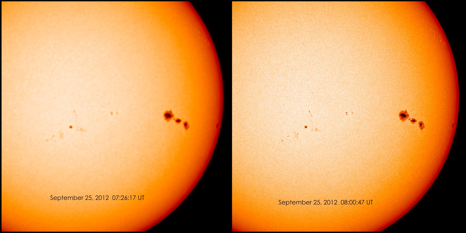

Oct. 10, 2012

On 3 August 1964, Command number 655-268 issued by Central Committee of Communist Party gave Soviet Chief Designer Korolev the objective of putting one man on the moon and returning him safely to earth - ahead of the Americans.

Prior to this, Korolev had concentrated on the earth orbit rendezvous method. His September 1963 L3 design was a 200 metric ton direct-lander requiring three launches of his giant N1 rocket and assembled in low earth orbit. This L3 spacecraft would make a precision 'blind' landing, homing in on a beacon aboard an L2 robotic lunar rover which had already been parked at a suitably flat touch-down point. The 138 metric ton trans-lunar injection stage would propel the L3 spacecraft towards the moon. The 40 metric ton lunar braking stage would ignite 200 to 300 km above the surface. After burnout, it would separate above the surface, allowing the 21 metric ton lunar soft landing/ascent stage, with variable-thrust engines to make a soft landing on the surface. The landing leg structure and soft landing engines would be left behind on the moon. The ascent stage would propel the 5 metric ton Soyuz L1 manned spacecraft back to earth. This capable but expensive spacecraft would have accommodated a crew of three for ten days of lunar surface exploration.

Two giant N1 rocket at the launch-pad

In order to beat the Americans, the redesigned N1-L3 exploited a variant of the Apollo program's lunar-orbit rendezvous method to reach the moon's surface. In this way the mission could be accomplished in just one launch of an improved N1 rocket. The L3 complex designed for the mission, with a total mass of 95 metric tons, would consist of the Block G translunar injection rocket stage; the LOK lunar orbiter; the LK lunar lander; and the Block D deceleration stage.

N-1 Soviet Manned Moon Rocket

The N1-L3 lunar flight plan evolved during the course of the program. By the end of LK development it was as follows:

The L3 complex would be injected into a 220 km, 51.8 degree inclination parking orbit of the earth. Up to one day could be spent in earth orbit before trans-lunar injection.

L3 complex separation (Orbiter SFS)

The Block G stage was ignited, putting the complex into a translunar trajectory. The Block G then separated.

During a 3.5 day translunar coast the Block D stage would perform two mid-course corrections. It then would brake the LOK/LK/Block D stack into an equatorial elliptical lunar orbit. The Block D would be restarted twice to adjust the orbit, first to a circular 110 km orbit, then to bring the pericynthion down to 14 km. The Block D could restarted for up to 4 days in lunar orbit.

The LK pilot would spacewalk from the LOK to the LK and check out the lander and Block D systems.

Russian manned lunar lander. 3 launches, 1970.11.24 (Cosmos 379) to 1971.08.12 (Cosmos 434). The LK ('Lunniy korabl' - lunar craft) was the Soviet lunar lander - the Russian counterpart of the American LM Lunar Module.

LK at Korolev

The LK was to have landed a single Soviet citizen on the moon before the Americans, winning the moon race. It completed development and test flown very successfully in earth orbit, but never reached the moon because the N1 booster required to take it to the moon never had a successful flight.

Because the translunar payload of the Russian N1 rocket was only 70% that of the American Saturn V, the LK differed in many ways from the LM. It had a different landing profile; it was only 1/3 the weight of the LM; it was limited to a crew of one; it had no docking tunnel (the cosmonaut had to space walk from the LK to the LOK lunar orbiter). Unlike the LM, the LK did not use a separate descent stage to go from lunar orbit to landing on the surface. A braking stage, the Block D, took the LK out of lunar orbit and slowed it to 100 m/s at an altitude of 4 km above the lunar surface. From there the LK used the engines of its Block E stage to soft land on the moon. The Block E also served as the ascent stage to return the LK to lunar orbit.

LK Landing Profile - Landing and abort profile of the LK lander. Credit: Mark Wade

The LK consisted of four primary modules:

    - The LPU landing gear, which allowed landing on the lunar surface. The LPU remained behind on the lunar surface, acting as a launch pad for the rest of the LK
    - The Block E rocket stage, which soft landed the LK on the moon and returned it to lunar orbit
    - The Lunar Cabin, the pressurized semi-spherical cabin where the cosmonaut was located
    - The Integrated Orientation System, a pod of small thrusters to orient the spacecraft. Atop the pod was the large hexagonal grid of the Kontakt docking system

Consider now the LK in depth. This article is organized into the following main sections:

    - The N1-L3 Lunar Mission Profile
    - Development of the LK
    - LK Flight Tests
    - Technical Description of the LK

The LK decent

The LK/Block D then separated from the LOK. The LK was capable of 72 hours of autonomous operation, 48 hours of which would normally be on the lunar surface. As it approached the landing site, the Block D began its main burn and braked the LK from to 100 m/s at four kilometers above the lunar surface. (Later in development this was reduced to 1.5 to 2.0 km above the surface). The Block D then separated and crashed on the moon about 4 km from the separation point.

LK landing on the Moon

The landing radar acquired the surface at an altitude of 3000 m. The LK's Block E stage then ignited its engines at full 2,050 kg thrust until vertical velocity reached zero. The engine was then throttled back to 850 kgf hover thrust and maneuvered to a soft landing on the surface. Propellant allowance for the whole maneuver was 280 kg, which allowed about 50 seconds hover time to divert to an alternate landing point up to 100 m away from that originally selected by the automated system. Later in development there was less than a minute total for the landing maneuver, including only 15 to 20 seconds of hover time.

LK Egress Tests

Image above: Another view of LK egress tests. This view makes clear the large size of the backpack of the Kretchet suit and the tight squeeze getting into and out of the LK lander. Credit: Filin

Four hours would be sent in surface operations on the first landing. The cosmonaut would exit the LK to the lunar surface. The space suit was limited to 1.5 hours on the surface at a time. The first Soviet space walk was to consist of: planting the flag; deployment of a very limited array of scientific instruments; taking soil samples; photography of the landscape; and cosmonaut commentary on the lunar surface. The LK could spend a total of from six to 48 hours on the lunar surface on later flights.

After returning to the LK's Lunar Cabin, the cosmonaut would seal the lunar samples in a hermetic container and then repressurise the cabin. The LK Lunar Cabin and Block E ascent stage would then take-off from the LK landing gear (LPU) and fly back into lunar orbit. The LOK orbiter would rendezvous and dock with the LOK using the 'Kontakt' system. The LK cosmonaut then space-walked from the LK back to the LOK with the lunar samples. The LK was then cast off.

LK landed on the Moon, EVA. Image : Screen capture from Celestia

After up to one additional day in lunar orbit, the LOK's Block I engine would put the LOK into trans-earth trajectory. 3.5 days was to be spent on the coast back to earth with two midcourse corrections en route. Before re-entry, the descent module separated from the LOK with the two cosmonauts aboard. It re-entered the earth's atmosphere over the South Pole at 11 km/sec, skipped back out to space after slowing down to 7.5 km/s, then soared 5,000 km before making final re-entry and landing on the territory of the USSR.

Krechet Lunar Spacesuit

Krechet lunar space suit as displayed at NPO Zvezda. As in the Orlan suit still used on Mir, the cosmonaut entered the suit by swinging open a hatch at the rear. The backpack containing the life support system was housed in the backpack which made up the hatch door. As in Apollo, the gold-coated outer visor of the helmet reflected ultra-violet radiation. The integrated Kretchet design meant that no external hoses were required as in the American Apollo suit. Credit: Andy Salmon

Development of the LK

The N1-L3 project was too big for one enterprise. Korolev's OKB-1 was assigned general management of the project. V M Filin was named manager for the LK within OKB-1. However detailed design, qualification, and construction of the LK Block E engine system was subcontracted to Yangel's OKB-586 in Dnepropetrovsk, Ukraine.

The advance design project for the N1-L3 was completed on 30 December 1964. The decree for production of 16 shipsets of spacecraft and boosters was issued on 26 January 1965. The N1-L3 was to manufactured to the following schedule: 4 in 1966; 6 in 1967; and 6 in 1968. The plan was for the first launch of the N1 to be in the first quarter of 1966, with the first lunar landings in 1967 to 1968, ahead of the American goal of 1969.

But as soon as detailed design of the LK began it was realized that the mass of the spacecraft in the draft project was completely unrealistic. The young engineers that had done the preliminary LK design had made numerous absurd assumptions. They had assumed a soft landing delta v of only 30 to 40 m/s (200 to 300 m/s was a more realistic estimate). A thirty degree braking angle was assumed after separation, but at this angle the radio altimeter couldn't detect the surface. Such optimistic assumptions resulted in the draft project putting the mass of the LK at 2 metric tons, with a crew of two. (The final LK would have a mass of 5.5 metric tons and be able to accommodate only one cosmonaut!).

Still, Yangel wanted to be sure to leave room for a crew of two in the cabin. But it was quickly discovered that this simply could not be done within the 40 to 50 metric ton low earth payload allotment for the LK/Block D. Given the original mis-estimate, throughout the project weight reduction was a constant concern. A separate descent stage would have had greater economy, but this presented numerous other problems not well understood when the project started. The Chief Designers offered prizes of 50 to 60 rubles per kilogram of weight reduction identified by project engineers. 500 kg was saved just by optimizing the rendezvous orbit.

LK First Mockup

The capability and accuracy of the landing radar system was the crucial first problem in development. The prompt and precise determination of the velocity and altitude of the LK after separation from the Block D was the key to minimizing propellant usage for the landing and determined the sizing of the whole LK vehicle (due to the propellant reserves required for touchdown and hover maneuvers).

The landing radar system was designated Planeta. Planeta consisted of four antennae, with their beams arranged in an asymmetric pyramid. Three determined the velocity vector using Doppler, while the fourth beam, in the central position, determined altitude above the surface. The system was simple and reliable. It was later proven on the Luna Ye-8 automated lunar sample return probes.

Numerous problems had to be solved regarding the reflection of the radar beam from the surface - problems analogous to those tackled a decade later in America in the design of stealth aircraft. Tests of the Planeta system aboard MiG-17 aircraft indicated that the initial radar reflectivity assumptions were wrong by several orders of magnitude.

Ignition of the Block E stage was commanded automatically by the Planeta system when the LK was 3 km from the touchdown point. After eliminating the vertical velocity, the final landing maneuver was commanded by the cosmonaut. Landing was made in the deep throttle range of the Block E. Engine shutoff was commanded automatically by the Planeta system.

OKB-1 Chief Designer Mishin allowed only a 280 kg propellant reserve for the entire landing maneuver. This constraint prolonged development of the Planeta system. In 1967 Yangel finally went to the Chief Designer's committee and informed them that he could not meet the requirement for two complete lunar landers until 1971.

Soviet LK lunar lander compared to US Lunar Module (LEM)

In 1968 the L3 scheme was overhauled. The original scheme had assumed a landing on the lunar equator. This meant that the LOK orbiter would pass over the landing site once per orbit, every hour. For the ascent of the LK to the rendezvous orbit in this case, a simple gyroscopic platform could accomplish the launch, as was used on the V-2 and R-7 missiles.

At landing sites away from the equator, within two to three orbits the LOK orbital plane would move too far away from the landing site to make such a pre-programmed ascent into the rendezvous orbit. Therefore a new type of guidance system was required. There were three possible choices:

    - Install a full-capability inertial navigation unit. This would allow the LK to perform a complex dog-leg maneuver during ascent to reach the plane of the LOK orbit (this was the American LM solution)
    - Use a strap-down gyroscopic platform to steer the LK in a pre-programmed deviation from its vertical axis until the LOK orbital plane position was reached.
    - Use the existing platform but develop a pre-set program of yaw angles, set before launch.

The second alternative was chosen. The LK would use the gyro platform to begin a bank maneuver at 25 to 30 km altitude. The program calculated the angle of tangency and the function of the cut-off of the LK engine. Soviet computer technology was not good enough at that time to equip the LK with an on-board re-programmable digital system. So instead an analogue parametric calculator was developed that took into account all conceivable problems and emergencies and the times at which they could occur. The resulting system was very effective and represented the major avionics system development for the LK.

LK drawing

A major difficulty during development was getting the cabin centre of mass on the thrust axis. It could not deviate more than 30 mm from the thrust axis or stable flight of the LK would not be possible. This requirement dictated the design of the propellant tanks of the Block E stage and Integrated Orientation System; required the development of special restraints for the cosmonaut in the cabin; and dictated the placement of equipment on the exterior of the LK. In particular the location of the heavy batteries was continually shifted during development.

LPU Development

The LPU - lunniy posadocnie ustroistviy - was the landing leg assembly of the LK. It would remain behind on the surface, acting as a launch pad for the Block E rocket stage. .Therefore the LPU not only to had to absorb the shock of landing, but provide a level base for the ascent stage as well. All systems not necessary for ascent were attached to it. A A Sarkisyan was in charge of LPU design.

The overall LK mass problem meant that there was only sufficient reserve propellant to move no more than 100 m from the original landing point selected by the automated system. Studies of Ranger photographs of the lunar surface indicated that the 100 m requirement meant that it was most likely the LK would land in a crater of 7 m diameter. This translated into the specification that the LPU be able to handle slopes of 30 degrees with the LK centre of gravity being 2.5 m above the surface. The requirement for high confidence unmanned landings also played a role in the stiff requirement.

The minimum design, as used on the US Surveyor, was three legs. But a three legged craft would require double the span of a four legged design for the same stability, and could not meet the thirty degree slope requirement. The design of the LPU was such an 'interesting' engineering problem that engineers from many sections of OKB-1 and Yangel's bureau proposed solutions. In the end over twenty variants of LPU landing gear layouts were studied, including toroidal rings, within which the LPU equipment would be housed, and some bizarre water-stabilized designs.

 LK LPU-Draft & Final

Image above: Detailed design of the LPU landing gear. At the top: design at the stage of LK draft project. At the bottom: the final production design.

Many of these ingenious approaches were too complex and mechanically risky. Finally V H Shaurov conceived the idea of 'nesting' engines - engines that would fire DOWNWARD at the instant of touchdown to remove all tipping moments from the spacecraft. This 'active' method of touchdown would reduce the complexity of the gear themselves while meeting the 30 degree requirement. In the end two gear schemes - passive (Feoktistov) and active (Shaurov) - were studied using scale models. Volcanic tuff believed to resemble the lunar regolith was imported from Armenia to simulate the lunar surface. A 300 x 400 mm sand pit was modeled with the tuff, including craters. The tests proved the active system, which was used on the LK.

A full scale mock-up of the final LPU design was built and tested. The shock absorbing techniques developed for the LK gear were later used in the androgynous APAS docking systems developed for Apollo-Soyuz and Mir. Kiselev proposed additional development of an altimeter-triggered soft landing rocket to cancel all vertical velocity, as was done for earth landings of the Soyuz system. But there was no time to develop the system.

Mounted on the LPU were those systems not required after the landing on the moon: the landing altimeter, parabolic antennae, chemical batteries, and three water tanks for the evaporative cooling system (a fourth was added late in development to trim the centre of gravity).

Lunar Cabin

A cabin environment using pure oxygen at 0.40 atmospheres was considered, but the need to develop special armatures, fire-proof materials, and the safety of the cosmonaut resulted in this being rejected. So the cabin environment selected was air at 0.74 atmospheres. This meant the cabin pressure vessel had to be twice as heavy, but this was considered worth it from a crew safety point of view.

LK interior

Soviet experience in manual control of spacecraft was limited at the time of LK development. The development team had to return to first principles in determining the control layout and the position of the cosmonaut. The challenging requirements included the need to operate the controls in a pressurized space suit in the event of cabin depressurization. Therefore foot pedals couldn't be used as in a fixed wing aircraft or helicopter. The design team consulted with helicopter and VTOL specialists at aviation design bureaus to solve these problems.

LK interior right

Development of the correct arrangement and placement of cabin control panels and windows was a long trial-and-error process. It was determined that the optimum viewing angle downwards for landing was 7 degrees. This lower view port was equipped with a collimator for predicting the landing point.

LK interior left

The Kretchet spacesuit developed, the ancestor of those still used on Mir today, could be entered through a hatch in the back. There was an elaborate system of braces and tie-down strips to fix the cosmonaut in a standing position during spacecraft maneuvers. This was because it was necessary to keep the centre of mass of the cosmonaut on the thrust axis of the engine.

Ingress/egress development was conducted again by trial-and-error, using full-size LK and suit mock-ups. It was found that the standard hatch developed for the Soyuz orbital module was too narrow for the cosmonaut in the lunar suit. So a special oval hatch had to be developed. This was a controversial solution but was finally approved. The asymmetric mass of the cosmonaut's ladder had to be balanced by placement of equipment on the other side.

LK panel

Due to weight considerations, no automatic docking system could be considered, as was used on the Soyuz spacecraft. The system objectives were minimum weight, manual operation, and tolerance to low accuracy docking. Since the cosmonaut would spacewalk from the LOK to the LK and back, no hard dock system, with system connections and a hermetic seal between the spacecraft, was required. The Kontakt system that was developed used a snare-like probe on the active LOK spacecraft. The LK was the passive vehicle, and was equipped with a 1.8 meter diameter, lightweight hexagonal alloy grid. Each of the 108 hexagons was a potential receptacle for the LOK's docking probe.

LK interior back

The Kontakt system was to have been tested on a series of earth orbit test flights using Soyuz spacecraft. These were postponed as continued N1 launch failures pushed the date of any possible lunar mission further and further back. In April 1969, two separate docking missions were planned for late 1969/early 1970. After Apollo 11's successful lunar landing, the development and launch of the Salyut space station (to beat the American Skylab) took priority. By December 1970, Kontakt missions were scheduled only after Salyut was successfully flown. Kontakt development was finally terminated in October 1971.

Block E Development

Originally development of the Block E landing/ascent stage was considered the pacing item in LK development. Drawings for the Block E were already issued in parallel with the draft project. The original specification of 510 kg empty mass for the stage could not be met. There were constant mass allocation fights between the rocket block design team and the cabin design team.

The LK variable-thrust, restartable engines represented a huge engineering development task. Unusually, Yangel decided to develop the system within his own OKB rather than entrust it to one of the traditional engine design bureau. New materials and new mechanical solutions were required to obtain a reliable, safe, redundant, durable engine that could be used over a wide variation of payload mass. In charge of Block E engine development was Ivan Ivanovich Ivanov, known to all as I-Cubed.

Close-up view of the engines of the LK exhibited at Korolev School

A key problem in design of both the Block E and the LPU was the flow of gases reflected from the surface during touchdown. In Apollo, the descent stage and its engine were left behind on the lunar surface; therefore it did not matter if the descent engine was damaged on landing (as actually occurred several times). But the LK used the same engine for landing and ascent from the surface. A hydrodynamic design had to be found that would prevent any damage to the engines during the landing maneuver. The final approach was streamlined propellant tanks for the Block E, which allowed the gases to flow up and away from the LPU during landing. The Block E engines were also equipped with clamshell doors, which closed at engine shut-off and prevented damage from foreign particles while the LK was on the lunar surface.

The propellant tanks were of unusual form. There were not only external gas flow considerations, but their geometry had to be specifically designed to keep the centre of mass within limits during the landing and ascent to orbit. Since the oxidizer was consumed at twice the rate as the fuel, the geometry had to accommodate this fact. Numerous tank layouts were studied before the optimum compromise between geometry and minimum mass was achieved. The self-igniting storable N2O4/UDMH propellants were stored in nested tanks of identical 1.2 cubic meter volumes.

Integrated Orientation System

The Integrated Orientation System was mounted above the Lunar Cabin. Yangel had no experience in microthrusters, so development of this system was subcontracted to Isayev. The same N2O4/UDMH propellant combination was used as in the Block E. The forward mounting of the package meant that the installation was 'unclean' - i.e. it introduced not only motion around the centre of gravity of the LK, but translation motions as well. The thrusters were arranged in two independent, redundant systems. In each system 2 x 40 kgf thrusters provided pitch; 2 x 40 kgf yaw; and 4 x 10 kgf for roll. Propellant totaling 100 kg was stored in two tanks. The problem arose how to preserve the centre of mass of the module on the main thrust line of the LK. The solution was to enclose the oxidizer tank within the propellant tank in a double-walled barrel construction.

 LK cutaway description (in Russian)

The thrusters were pressure-fed using internal diaphragms. This was the first use of such a technique in Soviet spacecraft, and a new steel alloy was developed by Stepanov for the purpose. The tanks were pressurized to 10 atmospheres by helium gas. Operation of the thrusters for continuous periods of up to ten seconds required development of new materials for the nozzles - niobium and graphite. Minimum thrust impulse was as lows as 9 milliseconds. The nozzles were canted 20 degrees from the horizontal when studies revealed that 95 out of 100 times a straight-through design would lose propellant after engine shutoff. This resulted in a mass savings to the LK of 12.5 kg.

LK Development

When the final drawings were reviewed, there was a major fight between the Yangel and Korolev bureaus over a 12 kg 'deficit' in the computed total mass out of the five metric ton total. Korolev's bureau used this to put the entire design into question. After frantic study, the difference was traced to calculation involving the inert gas used for propellant tank membrane pressurization.

Vibration and environmental tests were conducted on equipment at selected stages of fabrication and assembly. Flight tests were conducted of some components.

Military engineering experts from the Baikonur Cosmodrome had to review the design in order for it to be cleared for use at the launch site. They were experienced in missiles and could not understand the unpressurised operation of some of the equipment in a vacuum, the lack of aerodynamic fairings for cable runs, missing shrouds around the cables, etc.

LK lunar lander in assembly hall

Mock-ups and test stands used in LK development included:

    - Egress procedures mock-up. This was the first LK mock-up
    - Electrical test stand ('iron bird') to confirm logic and algorithms for control systems.
    - Electrical mock-up
    - Environmental test mock-up of Block E. This was tested in special vacuum / insolation environmental chambers. It was also used in heat balance studies.
    - Mock-up for antenna tests
    - Three Block E's for firing tests
    - Design of the landing system and cosmonaut training were accomplished on a specially-equipped Mi-4 helicopter, special test stands, and various partial task simulators.

LK Flight Tests

The T1K and T2K versions of the LOK and LK, respectively, were designed for independent earth orbital flight tests of the spacecraft. The T1K was to be launched by Proton and the T2K (also designated LK6/T2K ) by the Soyuz launch vehicle. This special 11A511L version of the Soyuz booster was equipped with a strengthened upper stage and bulbous fairing to accommodate the LK. An entire separate development team under Yu M Labutin was required to develop the special systems necessary for unmanned earth orbit test operations. 20 such systems were used on the T2K, including modifications of those developed for the Soyuz spacecraft. The Labutin team also had to decide what systems could logically be tested in earth orbit and which could not.

Three T2K's were built, in what was envisioned as a three flight program:

Flight 1 - Follow the standard engine profile Flight 2 - Induce or simulate various abort profiles Flight 3 - Reserve in case of failures on Flights 1 and 2

The flight programs were carefully constructed to allow time after each maneuver before the next one would be conducted. This allowed careful measurement of the resulting orbit after each maneuver in order to verify telemetered performance data, as well as time for playback of all telemetry, radio, and television of the events. It was difficult to arrange the schedule within the available LK battery amp-hours.

Inputs that would normally be done by the crew in the landing phase would have to be simulated and commanded from the ground. In order to accommodate the extra diagnostic and telemetry equipment, a second equipment section was installed on the T2K. Unique earth orbit sensors (solar/stellar, ion flow) were installed as well. These were required to orient the LK along the axis of the orbit.

The T2K crews worked day and night preparing the spacecraft, and finally the first T2K was shipped to Baikonur for launch. Each T2K was tested before flight in a vacuum insolation chamber. During vacuum chamber tests at Baikonur, one of the equipment sections decompressed. It was found to have had ten microscopic holes punched into it during transport. These were repaired. Finally fuelled and cleared for launch, the first T2K was launched on a sunny morning in November 1970. The three tests of the T2K went of without a hitch:

1970-11-24 - Cosmos 379 - T2K s/n 1: In demonstration of lunar landing and ascent maneuvers, first went from 192 km x 233 km orbit to 196 km x 1206 km orbit, with a delta V of 263 m/s representing the hover and landing maneuver after separation from the Block D. It them simulated the ascent maneuver to lunar orbit, going from a 188 km X 1198 km orbit to a 177 km X 14,041 km orbit with a delta V of 1,518 m/s.

1971-02-26 - Cosmos 398 - T2K s/n 2 - Second LK moon lander test using T2K version. Maneuver Summary: 189 km x 252 km to 186 km x 1189 km orbit, delta V 251 m/s; 186 km x 1189 km orbit to 200 km x 10,905 km orbit, delta V 1320 m/s.

1971-08-12 - Cosmos 434 - T2K s/n 3 - Final LK moon lander test using T2K version. Maneuver Summary: 188 km x 267 km orbit to 190 km X 1261 km orbit, delta V 266 m/s; 188 km x 1262 km orbit to 180 km X 11,384 km orbit, delta V 1333 m/s.

N1-L3 Moon Rocket Launch

End of the LK

A two-crew version of the LK was studied for support of the Zvezda DLB lunar base planned after the initial landings. Space was so limited that special recesses would have to made in the cabin wall to accommodate the helmets of the two suited cosmonauts. However this was a moot point, since the increased payload required major modifications of the engines and propellant tanks, which were specifically designed for the single-crew, 5,500 kg LK. In the end it was decided that this was not practical. Larger lunar landers were instead designed by Korolev's bureau using Soyuz return capsules and descent stages copied from the American lunar module layout.

Yangel died soon after completion of the successful T2K flights, content that he had done his part for the program.

LK landers are preserved at the MAI museum in Moscow (this was a flight model that was displayed at Eurodisneyland in 1997), the MAI museum at Orevo (an engineering article), St Petersburg, the Energia plant at Korolev, north of Moscow, and at KB Yuzhnoye in the Ukraine.

Soviet N1 moon rocket exploding & ending lunar program

Description of the LK

At the end of development the LK as designed had a mass of 5,560 kg, with the Block E stage weighing 2,950 kg. Takeoff mass from the lunar surface was 3,800 kg. The total height was 5.2 m. As with most aerospacecraft, the LK must be looked at from both a systems and a module viewpoint.

- LK Modules

- LPU

The LPU - lunniy posadocnie ustroistviy - was the landing leg assembly of the LK. The LPU was able to handle slopes of 30 degrees with the LK centre of gravity being 2.5 m above the surface. Solid propellant 'nesting' engines fired downward at the instant of touchdown to remove all tipping moments from the spacecraft. Mounted on the LPU were those systems not required after the landing on the moon: the landing altimeter, parabolic antennae, chemical batteries, and three water tanks for the evaporative cooling system (a fourth was added late in development to trim the centre of gravity). A video camera was externally mounted to give the ground a view of surface operations. It may be calculated from data given that the LPU, with its associated equipment, had a total mass of about 1,440 kg (5,560 kg LK mass - 280 kg descent propellant - 40 kg orientation system propellant used during descent - 3800 kg given as LK mass at start of ascent).


Image above: Numerous tests were conducted to determine the best hatch and ladder configuration for the cosmonaut in the bulky Kretchet spacesuit.

Block E Rocket Stage

The streamlined shape of the Block E allowed engine exhaust gases reflected from the lunar surface to flow up and away from the LK during landing. The Block E engines were equipped with clamshell doors, which closed at engine shut-off and prevented damage from lunar soil while the LK was on the lunar surface.

Total Block E mass has been given as 2,950 kg. It was stated that the original specification of 510 kg empty mass for the stage could not be met; assuming a 10% weight growth during development, the empty mass was probably around 550 kg. This would give a propellant load of 2,400 kg (volumetric capacity of the 2 x 1.2 cubic meter tanks was 2,600 kg). Propellant consumption in the landing maneuver was 280 kg, leaving about 2,100 kg for the ascent into orbit. The engines were rated to burn up to 2,900

Characteristics

Crew Size: 1. Orbital Storage: 30 days. Habitable Volume: 5.00 m3. RCS Coarse No x Thrust: 4 x 390 N. RCS Fine No x Thrust: 4 x 98 N. RCS total impulse: 245 kgf-sec. Spacecraft delta v: 2,700 m/s (8,800 ft/sec). Electric System: 30.00 kWh. Electric System: 0.50 average Kw.

AKA: T2K; LK; 11F94.
Gross mass: 5,560 kg (12,250 lb).
Unfuelled mass: 3,160 kg (6,960 lb).
Height: 5.20 m (17.00 ft).
Diameter: 2.25 m (7.38 ft).
Thrust: 20.10 kN (4,519 lbf).
Specific impulse: 315 s.
First Launch: 1970.11.24.
Last Launch: 1971.08.12.
Number: 3 .

Images, Videos, Text, Credits: Roscosmos / Mark Wade / Andy Salmon / Filin / Dan Roam / Korolev Space Center / RKK Energia / Orbiter.ch.

Greetings, Orbiter.ch