mercredi 9 décembre 2015

Cygnus Attached to Station Ready for Business


Orbital ATK / NASA - ISS CRS-4 Launch patch.

December 9, 2015


Image above: This rendering from a real-time computer animation shows the Cygnus spacecraft at the time of its capture with the Canadarm2 robotic arm. Credit: NASA TV.

Using the International Space Station’s robotic arm, Canadarm2, NASA Flight Engineer Kjell Lindgren successfully captured Orbital ATK’s Cygnus cargo vehicle at 6:19 a.m. EST. The space station crew and the robotics officer in mission control in Houston will position Cygnus for installation to the orbiting laboratory’s Earth-facing port of the Unity module.

The Orbital ATK Cygnus cargo ship was bolted into place on the International Space Station’s Earth-facing port of the Unity module at 9:26 a.m. EST. Cygnus will be the first cargo ship to be berthed to the Earth-facing port on the Unity module.
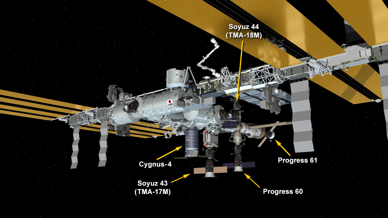

Image above: Dec. 9, 2015: International Space Station Configuration. (Clockwise from top) The Soyuz TMA-18M spacecraft is docked to the Poisk mini-research module. The ISS Progress 61 spacecraft is docked to the Zvezda service module. The ISS Progress 60 spacecraft is docked to the Pirs docking compartment. The Soyuz TMA-17M spacecraft is docked to the Rassvet mini-research module. The Cygnus-4 cargo craft is berthed to the Unity module.

The spacecraft’s arrival will support the crew members’ research off the Earth to benefit the Earth. The Cygnus is delivering more than 7,000 pounds of science and research, crew supplies and vehicle hardware to the orbital laboratory to support dozens of approximately 250 science and research investigations that will occur during Expeditions 45 and 46. Science payloads aboard Cygnus will offer a new life science facility that will support studies on cell cultures, bacteria and other microorganisms; a microsatellite deployer and the first microsatellite that will be deployed from the space station; and experiments that will study the behavior of gases and liquids, clarify the thermo-physical properties of molten steel, and evaluate flame-resistant textiles.

U.S. Cargo Craft Arrives at Space Station

Cygnus also will deliver replacement cargo items including a set of Microsoft HoloLens devices for use in NASA’s Sidekick project, a safety jet pack astronauts wear during spacewalks known as SAFER, and high pressure nitrogen and oxygen tanks to plug into the station’s air supply network.

The spacecraft will spend more than a month attached to the space station before its destructive re-entry into Earth’s atmosphere in January 2016, disposing of about 3,000 pounds of trash.

Related links:

NASA’s Sidekick project: https://www.nasa.gov/press-release/nasa-microsoft-collaborate-to-bring-science-fiction-to-science-fact/

Nitrogen and oxygen tanks: https://www.nasa.gov/content/air-supply-high-pressure-tanks-ready-for-space-station

International Space Station (ISS): https://www.nasa.gov/mission_pages/station/main/index.html

For more information about the Orbital ATK resupply mission, visit: http://www.nasa.gov/orbital

Images (mentioned), Video, Text, Credits: NASA/NASA TV/Mark Garcia.

Greetings, Orbiter.ch

Venus Climate Orbiter “AKATSUKI” Inserted Into Venus' Orbit


JAXA - Venus Climate Orbiter “AKATSUKI” Mission logo.

December 9, 2015

Artist's view of Venus Climate Orbiter “AKATSUKI” approaching Venus

The Japan Aerospace Exploration Agency (JAXA) successfully inserted the Venus Climate Orbiter “AKATSUKI” into the orbit circling around Venus.

Venus image taken by AKATSUKI immediately after its attitude control ejection:

 
Image above: By 1μm camera (IR1) at around 1:50 p.m. on Dec. 7 (Japan Standard Time) at the Venus altitude of about 68,000 km.


Image above: By Longwave IR camera (LIR) at around 2:19 p.m. on Dec. 7 (Japan Standard Time) at the Venus altitude of about 72,000 km.


Image above: By Ultraviolet Imager (UVI), at around 2:19 p.m. on Dec. 7 (Japan Standard Time) at the Venus altitude of about 72,000 km.

As a result of measuring and calculating the AKATSUKI’s orbit after its thrust ejection, the orbiter is now flying on the elliptical orbit at the apoapsis altitude of about 400 km and periapsis altitude of about 440,000 km from Venus. The orbit period is 13 days and 14 hours. We also found that the orbiter is flying in the same direction as that of Venus’s rotation. The AKATSUKI is in good health.

Orbit calculation result (as of Dec. 9)
 
Orbit pattern diagram

We will deploy the three scientific mission instruments namely the 2μm camera (IR2), the Lightning and Airglow Camera (LAC) and the Ultra-Stable oscillator (USO) and check their functions. JAXA will then perform initial observations with the above three instruments along with the three other instruments whose function has already been confirmed, the Ultraviolet Imager (UVI), the Longwave IR camera (LIR), and the 1μm camera (IR1) for about three months. At the same time, JAXA will also gradually adjust the orbit for shifting its elliptical orbit to the period of about nine days. The regular operation is scheduled to start in April, 2016.

Related links:

- Venus Climate Orbiter "AKATSUKI" (PLANET-C): http://global.jaxa.jp/projects/sat/planet_c/

- Venus Meteorology AKATSUKI (PLANET-C) (ISAS): http://www.isas.jaxa.jp/e/enterp/missions/akatsuki/index.shtml

For more information about Japan Aerospace Exploration Agency (JAXA), visit: http://global.jaxa.jp/

Images, Graphics, Text, Credits: Japan Aerospace Exploration Agency (JAXA)/National Research and Development Agency.

Best regards, Orbiter.ch

mardi 8 décembre 2015

NASA Releases New Visualization of Space Environment at Pluto


NASA - New Horizons Mission logo.

Dec. 8, 2015

This video shows a simulation of the space environment all the way out to Pluto in the months surrounding New Horizons’ July 2015 flyby. At the time, scientists at NASA’s Goddard Space Flight Center in Greenbelt, Maryland, worked with the New Horizons team to test how well their models—and other models contributed by scientists around the world—predicted the space environment at Pluto. Understanding the environment through which our spacecraft travel can ultimately help protect them from radiation and other potentially damaging effects. Visualizers at Goddard recently updated the movie of the model, creating this new release.

Simulating Space Weather at Pluto

Video above Credits: NASA's Goddard Space Flight Center Scientific Visualization Studio, the Space Weather Research Center (SWRC) and the Community-Coordinated Modeling Center (CCMC), Enlil and Dusan Odstrcil (GMU).

Though the vacuum of space is about a thousand times emptier than a laboratory vacuum, it’s still not completely empty. The sun releases a constant stream of particles called the solar wind—as well as occasional denser clouds of particles known as coronal mass ejections, or CMEs—both containing embedded magnetic fields. The density, speed, and temperature of these particles, as well as the direction and strength of the embedded magnetic fields, make up the space environment.

To map the space environment at Pluto, scientists combined the predictions of several models—and looked at events that had long since passed Earth.


Image above: This artist's concept depicts the New Horizons spacecraft during its July 2015 encounter with Pluto and one of the dwarf planet's moons, Charon. Image Credits: Johns Hopkins University Applied Physics Laboratory/Southwest Research Institute.

"We set the simulation to start in January of 2015, because the particles passing Pluto in July 2015 took some six months to make the journey from the sun," said Dusan Odstrcil, a space weather scientist at Goddard who created the Enlil model. The Enlil model, named for the Sumerian god of the wind, is one of the primary models used to simulate the space environment near Earth and is the basis for the New Horizons simulation. 

The new, combined model tracks CMEs longer than ever before. Because particles must travel for many months before reaching Pluto, the CMEs eventually spread out and merge with other CMEs and the solar wind to form larger clouds of particles and magnetic field. These combined clouds stretch out as they travel away from the sun, forming thin ring shapes by the time they reach Pluto—quite different from the typical balloon shape of CMEs seen here at Earth.

Related Links:

- Feature: “Scientists Simulate the Space Environment During NASA's New Horizons Flyby” (July 10, 2015): http://www.nasa.gov/feature/goddard/scientists-simulate-the-space-environment-during-nasas-new-horizons-flyby

- Download HD-quality multimedia related to this story from NASA Goddard’s Scientific Visualization Studio: http://svs.gsfc.nasa.gov/cgi-bin/details.cgi?aid=4392

- NASA's New Horizons mission website: http://www.nasa.gov/mission_pages/newhorizons/main/index.html

Image (mentioned), Video (mentioned), Text, Credits: NASA’s Goddard Space Flight Center/Sarah Frazier/Rob Garner.


Greetings, Orbiter.ch

Crescent Tethys and Rings & Prometheus Up Close


NASA - Cassini International logo.

Dec. 8, 2015

Crescent Tethys and Rings

Tethys, dwarfed by the scale of Saturn and its rings, appears as an elegant crescent in this image taken by NASA & ESA Cassini Spacecraft. Views like this are impossible from Earth, where we only see Saturn's moons as (more or less) fully illuminated disks.

The region of Saturn seen at left is on the planet's night side. Reflected light from the rings dimly illuminates the planet's northern hemisphere.

This view looks toward the anti-Saturn side of Tethys. North on Tethys is up and rotated 24 degrees to the left. The image was taken in visible light with the Cassini spacecraft wide-angle camera on Aug. 18, 2015.

The view was acquired at a distance of approximately 184,000 miles (296,000 kilometers) from Tethys. Image scale is 11 miles (18 kilometers) per pixel.

Prometheus Up Close

NASA & ESA Cassini spacecraft spied details on the pockmarked surface of Saturn's moon Prometheus (86 kilometers, or 53 miles across) during a moderately close flyby on Dec. 6, 2015. This is one of Cassini's highest resolution views of Prometheus, along with PIA18186 and PIA12593.

This view looks towards the anti-Saturn side of Prometheus. North on Prometheus is up. The image was taken in visible light with the Cassini spacecraft narrow-angle camera.

The view was acquired at a distance of approximately 23,000 miles (37,000 kilometers) from Prometheus and at a Sun-Prometheus-spacecraft, or phase, angle of 87 degrees. Image scale is 722 feet (220 meters) per pixel.

Prometheus orbits Saturn just interior to the narrow F ring, which is seen here at top.

The Cassini mission is a cooperative project of NASA, ESA (the European Space Agency) and the Italian Space Agency. The Jet Propulsion Laboratory, a division of the California Institute of Technology in Pasadena, manages the mission for NASA's Science Mission Directorate, Washington. The Cassini orbiter and its two onboard cameras were designed, developed and assembled at JPL. The imaging operations center is based at the Space Science Institute in Boulder, Colorado.

Related links:

PIA18186: http://photojournal.jpl.nasa.gov/catalog/PIA18186

PIA12593: http://photojournal.jpl.nasa.gov/catalog/PIA12593

For more information about the Cassini-Huygens mission visit http://saturn.jpl.nasa.gov or http://www.nasa.gov/cassini . The Cassini imaging team homepage is at http://ciclops.org .
ESA's Cassini-Huygens website: http://www.esa.int/Our_Activities/Space_Science/Cassini-Huygens

Images, Text, Credits: Credit: NASA/JPL-Caltech/Space Science Institute/Tony Greicius.

Best regards, Orbiter.ch

NASA's IMERG Measures Flooding Rainfall In Northwest England


NASA / JAXA - Global Precipitation Measurement (GPM) logo.

Dec. 8, 2015

In addition to destructive winds measured at 81 mph (70 knots) a powerful winter storm called "Desmond" dropped record rainfall in northwest England over the past weekend of Dec. 5 and 6. The rainfall was calculated and mapped at NASA's Goddard Space Flight Center in Greenbelt, Maryland using data from the Global Precipitation Measurement or GPM core satellite and other satellites.

 Unusually Heavy Rainfall and Flooding in Great Britain

Video above: Desmond's unusually heavy rainfall resulted in wide spread damaging floods. Data from NASA's Integrated Multi-satellitE Retrievals for GPM (IMERG) were used to estimate rainfall for the period from November 30 to December 7, 2015. This analysis found that some rainfall near the Irish Sea measured over 392 mm (~15.4 inches) during this period. As much as 304 mm (~12 inches) of rain were reported to have fallen in only 24 hours. Video Credits: SSAI/NASA/Hal Pierce.

Desmond's unusually heavy rainfall resulted in wide spread damaging floods. Data from NASA's Integrated Multi-satellitE Retrievals for GPM (IMERG) were used to estimate rainfall for the period from November 30 to December 7, 2015. This analysis found that some rainfall near the Irish Sea measured over 392 mm (~15.4 inches) during this period. As much as 304 mm (~12 inches) of rain were reported to have fallen in only 24 hours.


Image above: Data from NASA's IMERG were used to estimate rainfall for the period from Nov. 30 to Dec. 7, 2015 and found rainfall near the Irish Sea measured over 392 mm (~15.4 inches). Up to 304 mm (~12 inches) of rain were reported to have fallen in only 24 hours. Image Credits: SSAI/NASA/Hal Pierce.

The Integrated Multi-satellitE Retrievals for GPM (IMERG) creates a merged precipitation product from the GPM constellation of satellites. These satellites include DMSPs from the U.S. Department of Defense, GCOM-W from the Japan Aerospace Exploration Agency (JAXA), Megha-Tropiques from the Centre National D’etudies Spatiales (CNES) and Indian Space Research Organization (ISRO), NOAA series from the National Oceanic and Atmospheric Administration (NOAA), Suomi-NPP from NOAA-NASA, and MetOps from the European Organization for the Exploitation of Meteorological Satellites (EUMETSAT). All of the instruments (radiometers) onboard the constellation partners are inter-calibrated with information from the GPM Core Observatory’s GPM Microwave Imager (GMI) and Dual-frequency Precipitation Radar (DPR).

For more information about Global Precipitation Measurement (GPM), visit: http://www.nasa.gov/mission_pages/GPM/main/index.html and http://global.jaxa.jp/projects/sat/gpm/

Image (mentioned), Video (mentioned), Text, Credits: SSAI/NASA's Goddard Space Flight Center/Hal Pierce/Lynn Jenner.

Greetings, Orbiter.ch
Robot arm simulates close approach of ESA’s asteroid mission


ESA - Asteroid Impact Mission logo.

8 December 2015

The final approach to an asteroid has been practised for ESA’s proposed Asteroid Impact Mission using a real spacecraft camera mounted on a robot arm.

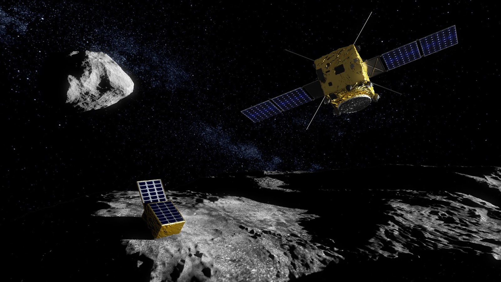
The 2020 AIM mission would find its way across deep space as usual with startrackers and radio ranging but the real challenge would come after arrival at its target Didymos double asteroids: picking its way around these unprecedented surroundings to close in on the smaller asteroid for detailed observations and setting down a lander.

Camera by model asteroid

The rehearsal took place at the Madrid headquarters of Spain’s GMV company, with ESA’s arm-mounted camera using dedicated navigation software to close in on a model asteroid.

“By including an actual navigation camera in the loop, we made the test as realistic as possible,” explains ESA guidance specialist Massimo Casasco.

As the Rosetta comet adventure showed last year, landing on a small body is no easy task.

AIM and lander

“One of AIM’s objectives is to put down a lander on the smaller of the Didymos asteroids using onboard autonomy and very limited resources,” says Ian Carnelli, ESA’s AIM project manager.

The low-budget AIM will avoid costly dedicated proximity sensors, instead calling on smart visual navigation software to track its motion over the surface. 

Testing camera-based navigation software for asteroid mission

In addition, it might reuse its laser communication package for measuring height above the surface.

ESA’s camera took images for the processing software to first select landmark ‘feature points’ within the field of view and then to follow them from frame to frame.

The camera itself has a detector that acquires the images, a ‘frame store’ for their intermediate storage and an image-processing chip to perform the feature tracking, before providing the information to AIM’s guidance and navigation computer.

Test camera

“The changing tracks of the various feature points over time (shown in purple in the video) are checked against the onward and rotational motion of the spacecraft to determine its position and orientation,” says ESA guidance expert Olivier Dubois-Matra.

“The ultimate goal for AIM is to demonstrate new ways to explore small Solar System bodies in the future,” adds Ian, “so we are testing this approach as fully as possible. In effect, the test bench is a fully fledged optical and robotic laboratory, testing AIM’s approach and the lander descent right down to deployment altitude.”

Camera on robot arm

With a launch window opening in October 2020, AIM would be humanity’s first mission to a double asteroid. Its first major design review next month will allow detailed design to begin in February.

The Mascot-2 lander is being designed and tested by Germany’s DLR space agency and is based on the lander scheduled to reach asteroid Ryugu as part of Japan’s Hayabusa-2 in July 2018.

NASA’s own Double Asteroid Redirection Test, or DART, probe will impact the same asteroid, with AIM providing detailed before-and-after mapping to help assess the effects and test planetary defence techniques.

Related article:

CubeSat companions for ESA’s asteroid mission:
http://orbiterchspacenews.blogspot.ch/2015/11/cubesat-companions-for-esas-asteroid.html

Related links:

AIM at a glance:

Asteroid Impact Mission: http://www.esa.int/Our_Activities/Space_Engineering_Technology/Asteroid_Impact_Mission/Asteroid_Impact_Mission2

AIM & AIDA:

Asteroid Impact & Deflection Assessment mission: http://www.esa.int/Our_Activities/Space_Engineering_Technology/Asteroid_Impact_Mission/Asteroid_Impact_Deflection_Assessment_mission

About AIM's mission:

Mission profile: http://www.esa.int/Our_Activities/Space_Engineering_Technology/Asteroid_Impact_Mission/Mission_profile

Spacecraft: http://www.esa.int/Our_Activities/Space_Engineering_Technology/Asteroid_Impact_Mission/Spacecraft

Target asteroid: http://www.esa.int/Our_Activities/Space_Engineering_Technology/Asteroid_Impact_Mission/Target_asteroid

Payload: http://www.esa.int/Our_Activities/Space_Engineering_Technology/Asteroid_Impact_Mission/Payload

Lander: http://www.esa.int/Our_Activities/Space_Engineering_Technology/Asteroid_Impact_Mission/Lander

CubeSats: http://www.esa.int/Our_Activities/Space_Engineering_Technology/Asteroid_Impact_Mission/CubeSats

Images, Video, Text, Credits: ESA/GMV/ScienceOffice.org.

Best regards, Orbiter.ch

dimanche 6 décembre 2015

Peering Through Titan's Haze


NASA - Cassini Mission to Saturn patch.

Dec. 6, 2015


This composite image shows an infrared view of Saturn's moon Titan from NASA's Cassini spacecraft, acquired during the mission's "T-114" flyby on Nov. 13, 2015. The spacecraft's visual and infrared mapping spectrometer (VIMS) instrument made these observations, in which blue represents wavelengths centered at 1.3 microns, green represents 2.0 microns, and red represents 5.0 microns. A view at visible wavelengths (centered around 0.5 microns) would show only Titan's hazy atmosphere (as in PIA14909). The near-infrared wavelengths in this image allow Cassini's vision to penetrate the haze and reveal the moon's surface.

During this Titan flyby, the spacecraft's closest-approach altitude was 6,200 miles (10,000 kilometers), which is considerably higher than those of typical flybys, which are around 750 miles (1,200 kilometers). The high flyby allowed VIMS to gather moderate-resolution views over wide areas (typically at a few kilometers per pixel).

The view looks toward terrain that is mostly on the Saturn-facing hemisphere of Titan. The scene features the parallel, dark, dune-filled regions named Fensal (to the north) and Aztlan (to the south), which form the shape of a sideways letter "H."

Artist's view of the Cassini spacecraft Titan Flyby

Several places on the image show the surface at higher resolution than elsewhere. These areas, called subframes, show more detail because they were acquired near closest approach. They have finer resolution, but cover smaller areas than data obtained when Cassini was farther away from Titan.

Near the limb at left, above center, is the best VIMS view so far of Titan's largest confirmed impact crater, Menrva (first seen by the RADAR instrument in PIA07365). Similarly detailed subframes show eastern Xanadu, the basin Hotei Regio, and channels within bright terrains east of Xanadu. (For Titan maps with named features see http://planetarynames.wr.usgs.gov/Page/TITAN/target.)

Due to the changing Saturnian seasons, in this late northern spring view, the illumination is significantly changed from that seen by VIMS during the "T-9" flyby on December 26, 2005 (PIA02145). The sun has moved higher in the sky in Titan's northern hemisphere, and lower in the sky in the south, as northern summer approaches. This change in the sun's angle with respect to Titan's surface has made high southern latitudes appear darker, while northern latitudes appear brighter.

Cassini Spacecraft Animation

The Cassini mission is a cooperative project of NASA, ESA (the European Space Agency) and the Italian Space Agency. The Jet Propulsion Laboratory, a division of the California Institute of Technology in Pasadena, manages the mission for NASA's Science Mission Directorate, Washington. The Cassini orbiter and its two onboard cameras were designed, developed and assembled at JPL. The visual and infrared mapping spectrometer team is based at the University of Arizona.

Related links:

PIA07365: http://photojournal.jpl.nasa.gov/catalog/PIA07365

PIA02145: http://photojournal.jpl.nasa.gov/catalog/PIA02145

For more information about the Cassini-Huygens mission http://saturn.jpl.nasa.gov/home/index.cfm. The visual and infrared mapping spectrometer team homepage is at http://www.vims.lpl.arizona.edu. ESA's website: http://www.esa.int/Our_Activities/Space_Science/Cassini-Huygens

Image, Video, Text, Credits: NASA/Martin Perez/ESA.

Best regards, Orbiter.ch