jeudi 3 février 2022

Photons Incoming: Webb Team Begins Aligning the Telescope


NASA / ESA / CSA-ASC - James Webb Space Telescope (JWST) patch.


Feb 3, 2022

This week, the three-month process of aligning the telescope began – and over the last day, Webb team members saw the first photons of starlight that traveled through the entire telescope and were detected by the Near Infrared Camera (NIRCam) instrument. This milestone marks the first of many steps to capture images that are at first unfocused and use them to slowly fine-tune the telescope. This is the very beginning of the process, but so far the initial results match expectations and simulations.

A team of engineers and scientists from Ball Aerospace, Space Telescope Science Institute, and NASA’s Goddard Space Flight Center will now use data taken with NIRCam to progressively align the telescope. The team developed and demonstrated the algorithms using a 1/6th scale model telescope testbed. They have simulated and rehearsed the process many times and are now ready to do this with Webb. The process will take place in seven phases over the next three months, culminating in a fully aligned telescope ready for instrument commissioning. The images taken by Webb during this period will not be “pretty” images like the new views of the universe Webb will unveil later this summer. They strictly serve the purpose of preparing the telescope for science.

James Webb Space Telescope (JWST)

To work together as a single mirror, the telescope’s 18 primary mirror segments need to match each other to a fraction of a wavelength of light – approximately 50 nanometers. To put this in perspective, if the Webb primary mirror were the size of the United States, each segment would be the size of Texas, and the team would need to line the height of those Texas-sized segments up with each other to an accuracy of about 1.5 inches.

Scott Acton and Chanda Walker of Ball Aerospace, along with Lee Feinberg of NASA Goddard, walk through the basic steps below:

“With deployment of the mirror segments now complete, and the instruments turned on, the team has begun the numerous steps required to prepare and calibrate the telescope to do its job. The telescope commissioning process will take much longer than previous space telescopes because Webb’s primary mirror consists of 18 individual mirror segments that need to work together as a single high-precision optical surface. The steps in the commissioning process include:

            1. Segment Image Identification
            2. Segment Alignment
            3. Image Stacking
            4. Coarse Phasing
            5. Fine Phasing
            6. Telescope Alignment Over Instrument Fields of View
            7. Iterate Alignment for Final Correction

1. Segment Image Identification

First, we need to align the telescope relative to the spacecraft. The spacecraft is capable of making extremely precise pointing moves, using “star trackers.” Think of star trackers as a GPS for spacecraft. At first, the position of the spacecraft from the star trackers does not match the position of each of the mirror segments.

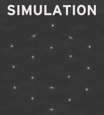
We are pointing the telescope at a bright, isolated star (HD 84406) to capture a series of images that are then stitched together to form a picture of that part of the sky. But remember, we don’t have just one mirror looking at this star; we have 18 mirrors, each of which is initially tilted towards a different part of the sky. As a result, we’ll actually capture 18 slightly shifted copies of the star – each one out of focus and uniquely distorted. We refer to these initial star-copies as “segment images.” In fact, depending on the starting positions of the mirrors, it may take multiple iterations to locate all 18 segments in one image.

Simulated example of a possible initial deployment showing 18 segment images

One by one, we will move the 18 mirror segments to determine which segment creates which segment image. After matching the mirror segments to their respective images, we can tilt the mirrors to bring all the images near a common point for further analysis. We call this arrangement an “image array.”

2. Segment Alignment

After we have the image array, we can perform Segment Alignment, which corrects most of the large positioning errors of the mirror segments.

We begin by defocusing the segment images by moving the secondary mirror slightly. Mathematical analysis, called Phase Retrieval, is applied to the defocused images to determine the precise positioning errors of the segments. Adjustments of the segments then result in 18 well-corrected “telescopes.” However, the segments still don’t work together as a single mirror.

Before: Simulated initial array of images

After: Simulated array of 18 corrected segments

3. Image Stacking

To put all of the light in a single place, each segment image must be stacked on top of one another. In the Image Stacking step, we move the individual segment images so that they fall precisely at the center of the field to produce one unified image. This process prepares the telescope for Coarse Phasing.

The stacking is performed sequentially in three groups (A-segments, B-segments, and C-segments).


Images above: Simulation of image stacking. First panel: Initial image mosaic. Second panel: A-segments stacked. Third panel: A- and B-segments stacked. Fourth panel: A-, B-, and C-segments stacked.

4. Coarse Phasing

Although Image Stacking puts all the light in one place on the detector, the segments are still acting as 18 small telescopes rather than one big one. The segments need to be lined up with each other with an accuracy smaller than the wavelength of the light.

Conducted three times during the commissioning process, Coarse Phasing measures and corrects the vertical displacement (piston difference) of the mirror segments. Using a technology known as Dispersed Fringe Sensing, we use NIRCam to capture light spectra from 20 separate pairings of mirror segments. The spectrum will resemble a barber pole pattern with a slope (or angle) determined by the piston difference of the two segments in the pairing.


Image above: In this simulation, the “Barber pole” patterns are created by the Disperse Fringe Sensor indicating a large piston error (top) or a small piston error (bottom).

5. Fine Phasing

Fine Phasing is also conducted three times, directly after each round of Coarse Phasing, and then routinely throughout Webb’s lifespan. These operations measure and correct the remaining alignment errors using the same defocusing method applied during Segment Alignment. However, instead of using the secondary mirror, we use special optical elements inside the science instrument which introduce varying amounts of defocus for each image (-8, -4, +4, and +8 waves of defocus).


Image above: A simulation of the defocused images used in Fine Phasing. The images (top) show defocus introduced to an almost aligned telescope. The analysis (bottom) indicates the errors associated with each telescope segment. Segments with very bright or dark colors need larger corrections.

6. Telescope Alignment Over Instrument Fields of View

After Fine Phasing, the telescope will be well aligned at one place in the NIRCam field of view. Now we need to extend the alignment to the rest of the instruments.

In this phase of the commissioning process, we make measurements at multiple locations, or field points, across each of the science instruments, as shown below. More variation in intensity indicates larger errors at that field point. An algorithm calculates the final corrections needed to achieve a well-aligned telescope across all science instruments.

Simulated analysis of the Field of View correction

7. Iterate Alignment for Final Correction

After applying the Field of View correction, the key thing left to address is the removal of any small, residual positioning errors in the primary mirror segments. We measure and make corrections using the Fine Phasing process. We will do a final check of the image quality across each of the science instruments; once this is verified, the wavefront sensing and controls process will be complete.

As we go through the seven steps, we may find that we need to iterate earlier steps as well. The process is flexible and modular to allow for iteration. After roughly three months of aligning the telescope, we will be ready to proceed to commissioning the instruments.”

Related links:

Near Infrared Camera (NIRCam) instrument: https://webb.nasa.gov/content/observatory/instruments/nircam.html

James Webb Space Telescope (JWST): https://www.nasa.gov/mission_pages/webb/main/index.html

Images, Animation (ESA), Text, Credits: Scott Acton, Webb lead wavefront sensing and control scientist, Ball Aerospace; Chanda Walker, Webb wavefront sensing and control scientist, Ball Aerospace; and Lee Feinberg, Webb optical telescope element manager, NASA’s Goddard Space Flight Center.

Greetings, Orbiter.ch

ISS orbital altitude correction scheduled for February 6


ISS - Russian Vehicles patch.


Feb 3, 2022

The planned correction of the height of the orbit of the International Space Station is planned on February 6, 2022 in order to form ballistic conditions before the launch of the manned spacecraft Soyuz MS-21 into orbit (March 18) and the landing of the Soyuz MS-19 descent vehicle (March 30).

International Space Station (ISS)

According to preliminary data from the ballistics and navigation support service of the TsNIIMash Mission Control Center (part of the Roscosmos State Corporation), at 12:30 Moscow time it is planned to issue a command to turn on the engines of the Progress MS-18 cargo ship docked to the Zvezda service module » Russian Segment of the ISS. They are expected to last 109.4 seconds and deliver an impulse of 0.2 m/s. It is planned that after the corrective maneuver, the average altitude of the station's orbit will increase by 400 meters - up to an altitude of 417.6 km.

The parameters of the ISS orbit after the corrective maneuver should be:

- Orbital period: 92.86 min;

- Orbital inclination: 51.66 degrees;

- Minimum orbit height: 415.67 km;

- Maximum orbit height: 439.62 km.


For the entire duration of the ISS flight, 314 corrections of its orbital height were made, including 165 with the help of the Progress cargo spacecraft engines.

Currently, a crew of Roscosmos cosmonauts Anton Shkaplerov (station commander) and Petr Dubrov, as well as NASA astronauts Mark Vande Hei, Raja Chari, Thomas Marshburn, Kayla Barron and European Space Agency astronaut Matthias Maurer are working on board the ISS.

Related links:

ROSCOSMOS Press Release: https://www.roscosmos.ru/33998/

TsNIIMash: https://www.roscosmos.ru/tag/cniimash/

MCC: https://www.roscosmos.ru/tag/cup/

Soyuz MS-19: https://www.roscosmos.ru/tag/sojuz-ms-19/

Soyuz MS-21: https://www.roscosmos.ru/tag/sojuz-ms-21/

International Space Station (ISS): https://www.roscosmos.ru/tag/mks/

Image, Text, Credits: ROSCOSMOS/MCC/Orbiter.ch Aerospace/Roland Berga.

Best regards, Orbiter.ch

Just add bubbles for cooler future spacecraft


ESA - European Space Agency emblem.


Feb 3, 2022

From soft drinks to hot tubs, people add bubbles to liquids for many different reasons. ESA engineers think bubbles produced at the verge of boiling point could help control the temperature of spacecraft in a more efficient and compact way. The main unknown is how bubbles will behave in differing gravities down to weightlessness, so researchers boarded parabolic flight aircraft for testing.

Flow-boiling test on parabolic flights

Keeping systems cool in space is a major engineering problem. Both machinery and people produce waste heat as they operate, but in the same way a vacuum flask keeps your coffee hot, the surrounding space environment prevents this heat from dissipating from spacecraft.

International Space Station (ISS)

The International Space Station (ISS), like many other crewed spacecraft, uses liquid circulated through tubes to absorb heat and pass it to external radiators – known as ‘single phase cooling’.

But ESA engineers are now looking into a more efficient variation, called ‘two phase cooling’ – already widely employed in terrestrial power plants and petrochemical processes.

ISS radiators for cooling

It is called ‘two phase’ because it employs two separate phases of matter: liquids and gases. Counter-intuitively, the coolant liquid is heated to the verge of boiling point as it flows through the structure being cooled. Contact with waste heat makes the liquid boil into bubbles of vapour. This ‘flow boiling’ approach can transport heat away much more quickly and efficiently.

Parabolic flight flow-boiling testing

“The heightened efficiency of heat transfer in boiling promises more compact and lighter thermal control system devices,” comments Sebastien Vincent-Bonnieu of ESA’s SciSpacE team. “Boiling is a complex phenomenon however, combining heat and mass transfers, hydrodynamics, instabilities and interfacial phenomena.

“Furthermore, gravity affects the fluid dynamics and may lead to unpredictable performances of thermal management systems in microgravity conditions. We therefore decided to perform experiments directly in (near) weightless environments using ESA’s 'Zero-G' Airbus A300 for parabolic flights.”

Parabolic Zero-G aircraft takeoff

Supported by ESA and Airbus Defence and Space, the Institute of Fluid Mechanics of Toulouse (IMFT) led by Prof. Catherine Colin designed a small compact loop for the study of flow boiling in weightlessness, fitting a circuit with a pump, a flow meter, preheaters, a condenser and associated tubing within the strictly limited volume available.

“This loop is planned to be installed aboard the ISS’s Columbus module, perhaps in the new version of the European Drawer Rack, EDR2,” explains Balazs Toth, ESA payload system engineer.

Operating experiment on parabolic flight

“To validate the design, a test version has been flown in ESA and CNES parabolic flight campaigns - the former producing bubbly flows in Moon, Mars and terrestrial gravities as well as in microgravity,” comments Olaf Schoele-Schulz, Project Manager from Airbus. “The experimental device proved fully operational, opening the way to follow-up investigations in-orbit.”

Cameras placed within the test device showed the bubbling liquid’s flow was unperturbed even as it moved a short distance downstream from 90° ‘elbow’ bends in the loop.

Boiling point

Microgravity boiling is a topic being probed by multiple European teams, variously performing experimental, theoretical and numerical research, coordinated through the Multiscale Analysis of Boiling Microgravity Application Programme or MAP project, overseen by Prof. Colin.

Bubble from boiling experiment on ISS

“Understanding and modelling of the boiling phenomenon requires complementary investigations at different scales: from microscopic scale with isolated bubbles to macroscale with flow boiling in a tube,” adds Julien Sebilleau from IMFT. “The Multiscale Boiling RUBI payload launched to the ISS in July 2019 and operated for a year and a half has been investigating boiling at individual bubble scale.”

Boiling. We research. You benefit

“Parabolic flights have meanwhile enabled larger-scale testing, but to go further, longer and better requires prolonged microgravity conditions,” adds Sebastien. “So we are looking forward to flying our flow-boiling experiment aboard the ISS.”

Related links:

ESA’s SciSpacE team: https://www.esa.int/Science_Exploration/Human_and_Robotic_Exploration/Research/Drop_fly_irradiate_ESA_s_SciSpace_research_programme

ESA’s 'Zero-G' Airbus A300: https://www.esa.int/Science_Exploration/Human_and_Robotic_Exploration/Research/Experience_weightlessness_on_board_the_Zero-G_Airbus

Institute of Fluid Mechanics of Toulouse (IMFT): https://www.imft.fr/en/accueil-english/

European Drawer Rack, EDR2: https://www.esa.int/Science_Exploration/Human_and_Robotic_Exploration/New_European_Drawer_Rack_set_for_Space_Station

Multiscale Analysis of Boiling Microgravity Application Programme or MAP: http://youbenefit.spaceflight.esa.int/docs/20180620/MAP.pdf

The Multiscale Boiling RUBI payload: https://www.esa.int/ESA_Multimedia/Images/2019/08/Rubi_payload

Space Engineering & Technology: https://www.esa.int/Enabling_Support/Space_Engineering_Technology

Animation, Images, Videos, Text, Credits: ESA/CNES/IMFT/NASA/ESA–T. Pesquet.

Greetings, Orbiter.ch

mercredi 2 février 2022

Health, Robotics and Construction Research on Station Today


ISS - Expedition 66 Mission patch.


Feb 2, 2022

Life science, robotics and space construction kept the Expedition 66 crew busy aboard the International Space Station on Wednesday. The orbital residents also worked on spacesuits and inspected a Russian module.

Eye checks continued on the orbiting lab with NASA astronaut Thomas Marshburn taking charge as crew medical officer during the afternoon. The three-time station astronaut used medical imaging gear, or optical coherence tomography, to scan the eyes and retinas of NASA Flight Engineers Kayla Barron and Raja Chari.


Image above: The waning gibbous Moon is pictured above the Earth’s horizon from the International Space Station. Image Credit: NASA.

Marshburn began his day studying how to produce and maintain nutrients during long-term space missions. Chari later worked on communications components inside a pair of U.S. spacesuits. Barron started her morning cleaning the Cell Biology Experiment Facility, an incubator with an artificial gravity generator.

NASA Flight Engineer Mark Vande Hei set up the free-flying Astrobee robotic assistants and tested an autonomous rendezvous algorithm for the ROAM technology demonstration. ESA (European Space Agency) astronaut Matthias Maurer resumed the Concrete Hardening experiment studying potential lunar and planetary construction techniques.

International Space Station (ISS). Animation Credit: ESA

Roscosmos Flight Engineer Pyotr Dubrov photographed the condition of window panes in the Zvezda service module for inspection by engineers on the ground. Station Commander Anton Shkaplerov transferred water from tanks in the ISS Progress 79 resupply ship into the space station.

Related links:

Expedition 66: https://www.nasa.gov/mission_pages/station/expeditions/expedition66/index.html

Produce and maintain nutrients: https://www.nasa.gov/mission_pages/station/research/experiments/explorer/Investigation.html?#id=7400

Cell Biology Experiment Facility: https://www.nasa.gov/mission_pages/station/research/experiments/explorer/Facility.html?#id=333

Astrobee: https://www.nasa.gov/mission_pages/station/research/experiments/explorer/Facility.html?#id=1891

ROAM: https://www.nasa.gov/mission_pages/station/research/experiments/explorer/Investigation.html?#id=8324

Concrete Hardening: https://www.nasa.gov/mission_pages/station/research/experiments/explorer/Investigation.html?#id=8538

Zvezda service module: https://www.nasa.gov/mission_pages/station/structure/elements/zvezda-service-module.html

Space Station Research and Technology: https://www.nasa.gov/mission_pages/station/research/overview.html

International Space Station (ISS): https://www.nasa.gov/mission_pages/station/main/index.html

Image (mentioned), Animation (mentioned), Text, Credits: NASA/Heidi Lavelle.

Best regards, Orbiter.ch

SpaceX Falcon 9 launches NROL-87


SpaceX - Falcon 9 / NROL-87 Mission patch.


Feb 2, 2022

Falcon 9 carrying NROL-87 liftoff

A SpaceX Falcon 9 rocket launched the NROL-87 mission for the National Reconnaissance Office (NRO) from Space Launch Complex 4 East (SLC-4E) at Vandenberg Space Force Base in California, on 2 February 2022, at 20:27 UTC (12:27 PST).

Falcon 9 launches NROL-87 and Falcon 9 first stage landing

Following stage separation, Falcon 9’s first stage (B1071) landed on Landing Zone 4 at Vandenberg Space Force Base in California.

This was the first launch and landing of this booster, which will be prepared for re-flight on another NRO mission later this year.

SpaceX: https://www.spacex.com/

Image, Video, Text, Credits: SpaceX/SciNews/Orbiter.ch Aerospace/Roland Berga.

Greetings, Orbiter.ch

An Expanse of Light


NASA - Chandra X-ray Observatory patch.


Feb 2, 2022

The recent launches of the James Webb Space Telescope (Webb) and the Imaging X-ray Polarimetry Explorer (IXPE) by NASA and its international partners are excellent reminders that the universe emits light or energy in many different forms. To fully investigate cosmic objects and phenomena, scientists need telescopes that can detect light across what is known as the electromagnetic spectrum.

Images Credits: X-ray: NASA/CXC/SAO; Optical: NASA/STScI, Palomar Observatory, DSS; Radio: NSF/NRAO/VLA; H-Alpha: LCO/IMACS/MMTF.

This gallery provides examples of the ways that different types of light from telescopes on the ground and in space can be combined. The common thread in each of these selections is data from NASA's Chandra X-ray Observatory, illustrating how X-rays — which are emitted by very hot and energetic processes — are found throughout the Universe.

R Aquarii:


This object is, in fact, a pair: a white dwarf star that steadily burns at a relatively cool temperature and a highly variable red giant. As they orbit each other, the white dwarf pulls material from the red giant onto its surface. Over time, enough of this material accumulates and triggers an explosion. Astronomers have seen such outbursts over recent decades. Evidence for much older outbursts is seen in the spectacular structures observed by NASA's Hubble Space Telescope (red and blue). X-ray data from Chandra (purple) shows how a jet from the white dwarf is striking material surrounding it and creating shock waves, similar to sonic booms from supersonic planes.

Cassiopeia A:


Chandra's observations of the Cassiopeia A supernova remnant have shown how individual elements from the exploded star are being cast off into space. In this image, X-rays reveal silicon (red), sulfur (yellow), calcium (green), and iron (light purple). The blue around the rim of the remnant reveals the blast wave from the explosion as it travels outward. This image also adds a layer of radio data of Cassiopeia A from the National Science Foundation's Karl Jansky Very Large Array (dark purple, blue, and white) and an optical image from Hubble (orange). Like X-rays, radio waves can penetrate thick clouds of gas and dust that lie between Earth and Cassiopeia A, providing additional information about this famous stellar explosion.

Guitar Nebula:


For the last decade or so, astronomers have been puzzled by the alignment of some jets of X-rays coming from very fast-moving pulsars (that is, spinning neutron stars) that shoot out into interstellar space at odd, unexpected angles. This is what astronomers see with PSR B2224+65, a pulsar found near the structure nicknamed the "Guitar Nebula" due to its shape in optical light (blue). An X-ray stream (pink) captured by Chandra is pointed nearly perpendicular to the guitar-shaped structure, originating from the magnetic poles of the pulsar.

Abell 2597:


Galaxy clusters, the largest structures in the universe held together by gravity, are dynamic environments containing individual galaxies and huge amounts of hot gas and dark matter. Often, an enormous black hole in the center of a cluster can help drive its behavior. In the galaxy cluster Abell 2597, a giant central supermassive black hole is driving the gas outward and creating bubbles, or voids, within it. This composite image of Abell 2597 includes X-rays from Chandra (blue), optical data from the Digitized Sky Survey (orange), and emission from hydrogen atoms in optical light from the Las Campanas Observatory in Chile (red).

NGC 4490:


When two galaxies are in the process of merging, the gravitational interaction can trigger waves of star formation. This is the case for NGC 4490, a spiral galaxy that has collided with a smaller galaxy to the upper right but not seen in this image. Scientists think that these two galaxies have already had their closest approach and are now separating from one another. Some of the point-like sources of X-rays represent stellar-mass black holes and neutron stars within the galaxy. In this image of NGC 4490, X-rays from Chandra (purple) have been combined with an optical image from Hubble (red, green, and blue).

Chandra X-ray Observatory. Animation Credits: NASA/CXC

NASA's Marshall Space Flight Center manages the Chandra program. The Smithsonian Astrophysical Observatory's Chandra X-ray Center controls science operations from Cambridge, Massachusetts, and flight operations from Burlington, Massachusetts.

Read more from NASA's Chandra X-ray Observatory: https://chandra.harvard.edu/photo/2022/archives/

For more Chandra images, multimedia and related materials, visit: http://www.nasa.gov/chandra

Images (mentioned), Animation (mentioned), Text, Credits: NASA/Lee Mohon/Marshall Space Flight Center/Molly Porter/Chandra X-ray Center/Megan Watzke.

Greetings, Orbiter.ch

NASA, Space Station Partners Approve First Axiom Mission Astronauts


Axiom Space logo.


Feb 2, 2022

NASA and its international partners approved crew members for Axiom Space’s first private astronaut mission to the International Space Station. The flight, called Axiom Mission 1 or Ax-1, is targeted to launch Wednesday, March 30, from Launch Complex 39A at NASA’s Kennedy Space Center in Florida on a flight-proven SpaceX Falcon 9 rocket. The Ax-1 crew will fly on Crew Dragon Endeavour to and from the space station. After 10 days in orbit, the Ax-1 crew will splash down off the coast of Florida.


Image above: Axiom Mission 1 astronauts, Larry Connor, left, Michael López-Alegría, Mark Pathy, and Eytan Stibbe, right. The astronauts cleared medical evaluations and are approved by the Multilateral Crew Operations Panel. Image Credit: Axiom Space.

Axiom Space astronauts Michael López-Alegría, Larry Connor, Mark Pathy, and Eytan Stibbe are prime crew members of the Ax-1 mission. López-Alegría, who was born in Spain, raised in California, and a former NASA astronaut, will serve as the mission commander. Connor, of Dayton, Ohio, will serve as pilot. Pathy, from Canada, and Stibbe, from Israel, will be mission specialists. The quartet is scheduled to spend eight days aboard the orbiting laboratory conducting science, education, and commercial activities before their return to Earth.

“This represents another significant milestone in our efforts to create a low-Earth orbit economy,” said Phil McAlister, director of commercial spaceflight at NASA. “I wish these Axiom crew members safe travels, and I hope they find their time in space productive and enjoyable.”

Proposed mission activities are still under review and will be approved prior to flight. Axiom previously revealed a microgravity research portfolio the Ax-1 crew intends to undertake in orbit in partnership with a variety of organizations on Earth. This research is sponsored by the ISS U.S. National Laboratory.

“The goal for the Ax-1 crew is to set a standard for all future private astronaut missions in terms of our preparation and professionalism,” López-Alegría said. “As the commander, I am proud of the work these crew members have put in to be ready to conduct meaningful work on the International Space Station and glad to see them meet the standards required of all astronauts flying to station since Expedition 1. Ax-1 is focused on a huge amount of science and outreach activities, and we look forward now to finalizing that flight program.”

The Ax-1 crew has been training at NASA’s Johnson Space Center in Houston and other NASA facilities since August 2021 to familiarize themselves with station systems, scientific facilities, and emergency procedures. The crew also has been training with NASA’s space station international partners at ESA (European Space Agency), as well as with launch contractor SpaceX at its facilities in Hawthorne, California, and at other locations in preparation for the mission.

NASA and Axiom mission operations teams began joint simulations in December for familiarization with the dynamic phases of the private astronauts’ flight to and from the space station. Joint simulations will continue in preparation for launch.

NASA continues to make rapid progress in its efforts to build a robust low-Earth orbit economy. The agency recently announced its selection of Axiom Space to begin negotiations for the second private astronaut mission. NASA also recently announced its selection of companies to develop designs of space stations and other commercial destinations in low-Earth orbit.

Prior to these new awards, NASA selected Axiom Space in January 2020 to design and develop commercial modules to attach to the station. Axiom recently completed the preliminary design review of two modules as well as the critical design review of the modules’ primary structure with NASA participation. Flight hardware for the first Axiom module is currently undergoing fabrication.

For more than 21 years, NASA has supported a continuous U.S. human presence in low-Earth orbit aboard the space station. The agency's goal is to enable a strong, commercial marketplace in low-Earth orbit with private industry where NASA is one of many customers. This strategy will provide services the government needs at a lower cost, enabling the agency to focus on its Artemis missions to the Moon in preparation for Mars while continuing to use low-Earth orbit as a training and proving ground for those deep space missions.

Find out about the Ax-1 mission at: https://www.axiomspace.com/ax1

Related links:

ISS U.S. National Laboratory: https://www.nasa.gov/mission_pages/station/research/nlab/index.html

Commercial Space: http://www.nasa.gov/exploration/commercial/index.html

Commercial Crew: https://www.nasa.gov/exploration/commercial/crew/index.html

International Space Station (ISS): https://www.nasa.gov/mission_pages/station/main/index.html

Image (mentioned), Text, Credits: NASA/Robert Margetta/Stephanie Schierholz/Josh Finch/JSC/Gary Jordan/Axiom Space/Beau Holder.

Best regards, Orbiter.ch